
Car anti-theft alarm circuit
The Easy Car Alarm circuit is designed to provide a cost-effective and efficient solution for vehicle anti-theft protection. The NE555 timer, a versatile integrated circuit, is configured in a monostable mode to create a delay function that is crucial for the operation of this alarm system. The circuit employs a minimal number of components, which not only simplifies the assembly process but also reduces the overall cost of the project.
The power switch (VT) is typically a transistor that acts as a relay, allowing the NE555 timer to control the ignition circuit of the vehicle. When the vehicle is parked and the S2 switch is set to the "a" position, the circuit becomes active. The charging of the capacitor (C) through the resistor (Ri) establishes a time delay, during which the vehicle owner can safely exit the vehicle. The gradual increase in voltage at the NE555 input pin is monitored, and once it exceeds the threshold, the output state changes, activating the power switch.
The ignition circuit can be disabled within a few seconds after the vehicle is parked, ensuring that if an unauthorized attempt to start the vehicle occurs, the engine will not start. The alarm function is integrated into this process, as the engine emits a sound when the ignition is disabled, alerting the owner or nearby individuals of the potential theft attempt.
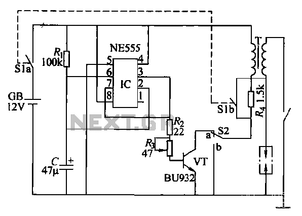
This design is particularly suitable for DIY enthusiasts and those looking for a straightforward solution to enhance vehicle security. The use of standard electronic components makes it accessible for assembly and modification, allowing for customization based on individual preferences or additional features. Overall, this Easy Car Alarm circuit serves as a practical and effective method to deter vehicle theft while being user-friendly and economically viable.This paragraph Easy Car Alarm circuit with the use of fewer components, easy to produce and so on. (1) circuit automobile anti-theft alarm circuit by the time base circuit NE555, power switch VT, the switch S2, the delay capacitor C and a resistor feet, ~ wind and other components, as shown in Figure 13-34. Sl (Sla, Slb) automotive ignition switch (open lock off). GB is a car battery, Re is the car with the ignition additional limiting resistor coil used. (2) circuit works in normal vehicle start-up operation , the switch S2 placed b-point, anti-theft circuit does not work. During the car is parked, S2 placed a point where if turned Sl, the + 12V voltage through Ri charges C IC so that pin and foot potential rise gradually while lC output of foot high level, so that VT conduction, the ignition circuit is turned on, the engine unit can start.
After a few seconds delay. c charging is completed, IC's feet and to foot potential rise when 8V, IC triggers internal flip, which feet from high to low, VT cut-off, the ignition circuit is turned off, automatic engine flameout, Cars can not be driven away. Starting off with the engine sound repeatedly, the equivalent of an alarm signal.
Related Circuits
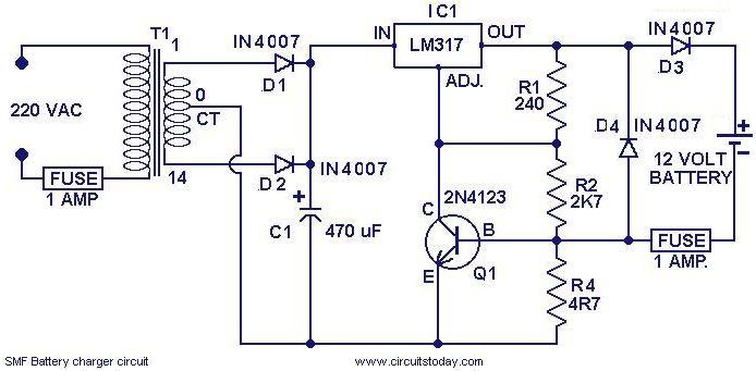
This is a simple charger circuit designed for charging sealed maintenance-free (SMF) batteries. The circuit is both current and voltage regulated, making it safe for charging SMF batteries with a rating of 1.2 AH. It can be modified slightly...
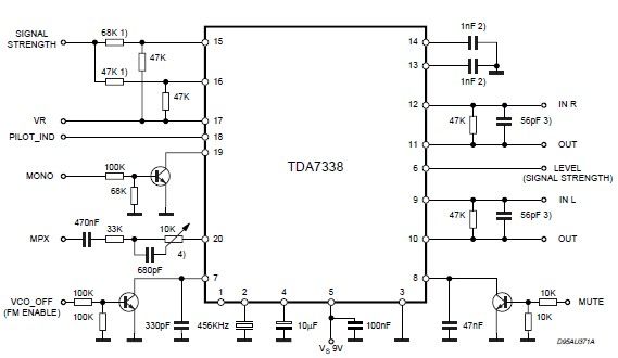
The pilot detector output is configured as an open collector output, necessitating the use of an external pull-up resistor. To set the decoder to "MONO," Pin 19 must be clamped to a voltage lower than 0.8V. The open collector output...
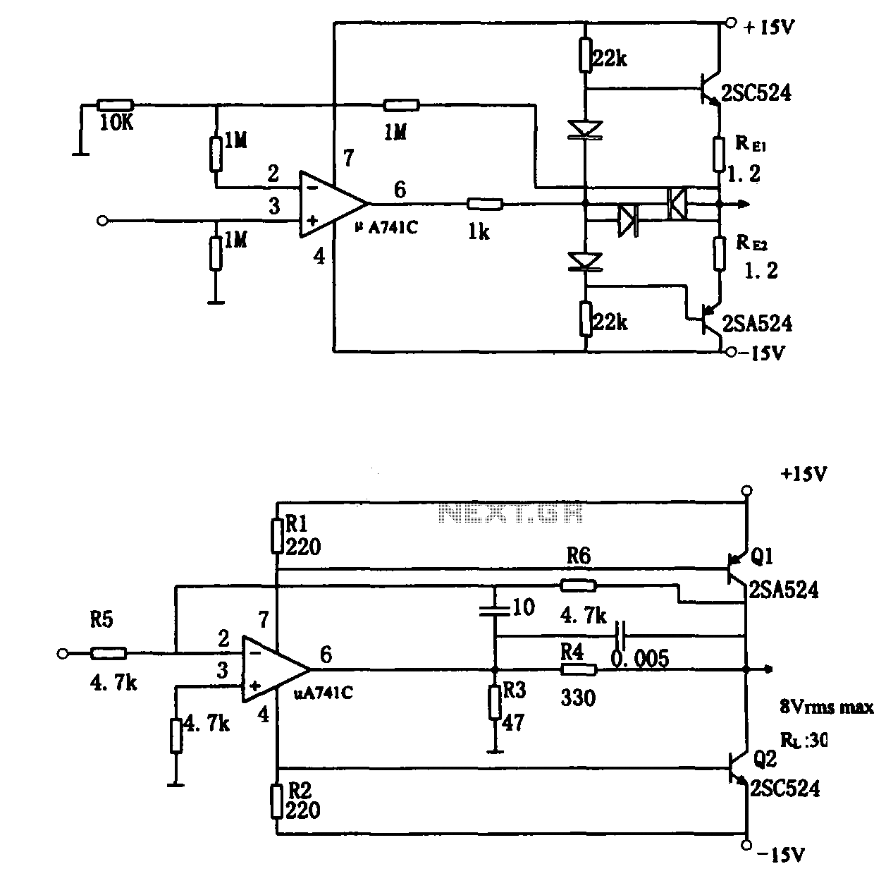
The direct coupling audio power amplifier utilizes an integrated operational amplifier. There are typically two practical configurations. The first configuration, depicted in (a), features a circuit structure that includes the output of the operational amplifier and a complementary symmetry...
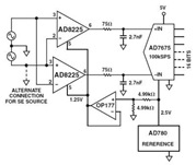
The Common Mode Rejection Ratio (CMRR) facilitates the rejection of high-frequency common-mode voltages, leading to the attenuation of elevated ambient noise levels from utility lines, industrial machinery, and other sources of radiation. The circuit diagram presented illustrates the advantages...
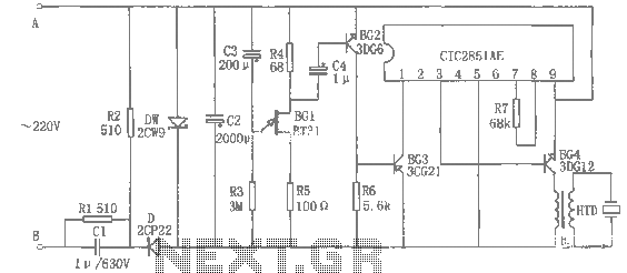
The rice cooker notification circuit operates as follows: When the rice cooker is in operation, both terminals A and B have a voltage of 0, meaning the entire circuit remains inactive. In the event that the rice cooker runs...
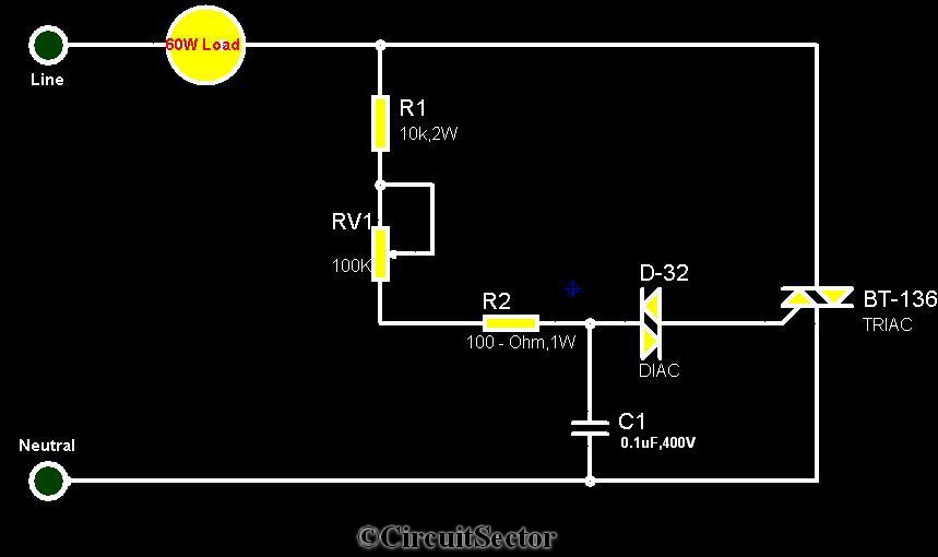
The circuit diagram presented is a triac-diac electronic fan regulator designed to reduce power consumption of electric fans, even at low speeds. Traditional resistor-inductor fan regulators tend to generate excess heat, wasting energy when the fan operates at lower...