
555 timer circuit
The NE555 timer is widely used for generating precise time delays and oscillations in various applications. In this specific configuration, it operates in monostable mode, where the output pulse duration is determined by the resistors and capacitor connected to it.
In the ten-minute timer circuit, the timing interval is set by selecting appropriate resistor (R1) and capacitor (C1) values. The relationship between the timing components and the output duration can be expressed by the formula:
\[ T = 1.1 \times R1 \times C1 \]
Here, T is the time in seconds, R1 is the resistance in ohms, and C1 is the capacitance in farads. For a ten-minute timer, R1 and C1 must be chosen carefully to meet this requirement.
Typically, a push-button switch is connected to the trigger pin of the NE555. When the switch is pressed, it sends a low signal to the trigger pin, causing the output pin to go high for the duration of the timing interval. Once the time elapses, the output returns to a low state.
Additionally, a diode may be included in the circuit to prevent any back-emf that could disrupt the timing process when the switch is released. The circuit may also incorporate an LED indicator connected to the output pin to visually signal when the timer is active.
Power supply requirements for the NE555 timer generally range from 4.5V to 15V, allowing for flexibility in various applications. Proper decoupling capacitors should be placed near the power pins to stabilize the voltage and reduce noise.
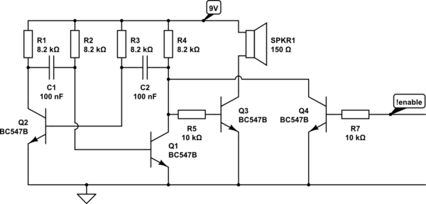
In summary, this ten-minute timer circuit utilizing the NE555 timer is a practical and widely applicable design that showcases the versatility of the 555 IC in timing applications.The schematic shown below is a 555 timer circuit. NE555 is a famous IC comes in 8 pin dip plastic package. There is a huge list of 555 IC circuits due to which this IC is very popular among electronics hobbiests, students and experimenters. The circuit mentioned here is a ten minutes timer, after pusing 🔗 External reference
Related Circuits
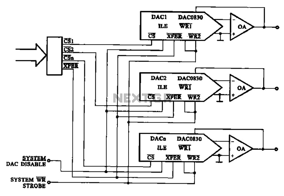
A multi-channel D/A converter circuit is presented, illustrating its fundamental structure. This circuit effectively converts encoded digital signals into multiplexed analog signal outputs. The multi-channel Digital-to-Analog (D/A) converter circuit is designed to facilitate the conversion of digital signals into corresponding...
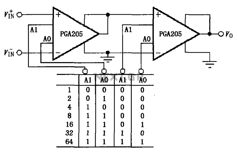
A binary gain step circuit is illustrated using the PGA205, which has a gain range of 1 to 64. The circuit employs two PGA205 devices in cascade, resulting in a total gain that is the product of the individual...
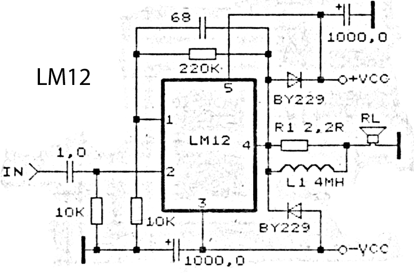
This is an amplifier circuit utilizing the LM12 integrated circuit as the primary amplifier. The amplifier delivers a power output of 150 watts and operates with a load impedance of 4 ohms. It is classified as a high-output power...
This little guide for every electronics tester would actually have to lie in the toolbox. You can have components such as resistors, capacitors, diodes, etc. of testing. T1 and T2 form a Darlington. Therefore only need a small base...
Any ideas? Is this circuit going to be standalone? Is there any other circuitry around it, perhaps a microcontroller? What circuitry does the timing device contain, or does it even contain electronics? Abdullah Kahraman Mar 22, '13 at 18:10....
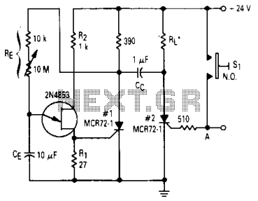
After one cycle of operation, SCR1 will be activated, resulting in a low voltage being applied to the UJT emitter circuit, which interrupts the tuning function. When pushbutton SI is pressed, or a positive pulse is applied at point...
Warning: include(partials/cookie-banner.php): Failed to open stream: Permission denied in /var/www/html/nextgr/view-circuit.php on line 713
Warning: include(): Failed opening 'partials/cookie-banner.php' for inclusion (include_path='.:/usr/share/php') in /var/www/html/nextgr/view-circuit.php on line 713