
Binary gain step circuit diagram by the PGA205
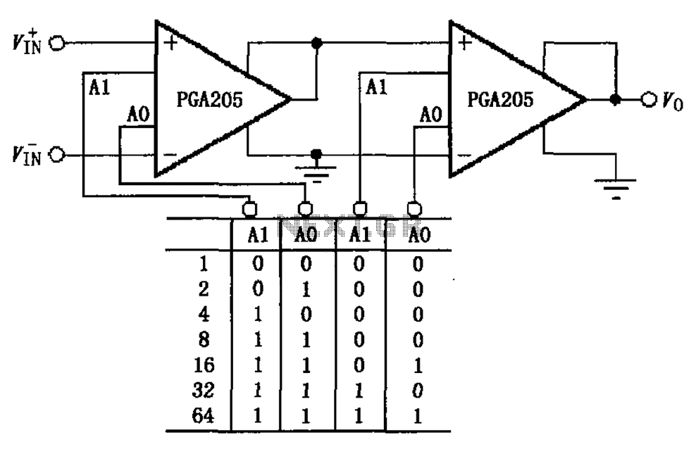
The binary gain step circuit utilizing the PGA205 operational amplifiers is designed to provide a versatile range of gain settings from 1 to 64, making it suitable for various signal processing applications. The configuration of two PGA205 devices in cascade allows for the multiplication of their individual gains, enhancing the overall gain flexibility of the circuit.
In this circuit, each PGA205 can be independently configured to achieve specific gain values, which are then multiplied together to determine the total gain of the system. This allows for precise control over the amplification process, enabling the circuit to adapt to different input signal levels effectively.
The PGA205 is a programmable gain amplifier that features a range of gain settings that can be controlled digitally. This capability is essential for applications requiring dynamic adjustment of gain in response to varying signal conditions. The gain settings can typically be adjusted through a digital interface, allowing for integration with microcontrollers or digital signal processors (DSPs).
The schematic of the circuit will typically include power supply connections, input and output terminals, and control lines for setting the gain of each PGA205. Capacitive coupling may be employed at the input and output stages to block DC offsets and ensure that only the AC component of the signal is amplified. Additionally, feedback resistors may be used to stabilize the gain and improve linearity across the operational range.
In summary, the binary gain step circuit using two PGA205 amplifiers in cascade configuration provides a robust solution for applications requiring adjustable gain with high precision and flexibility. The design facilitates easy integration into larger systems where gain control is necessary for optimal performance. Binary gain step circuit is shown by PGA205 constituted a gain range of 1 to 64. The circuit uses two PGA205 cascade with a total gain of the circuit is the product of a two-st age gain, that is G G1G2. Each PGA205 gain setting shown in Figure.
Related Circuits
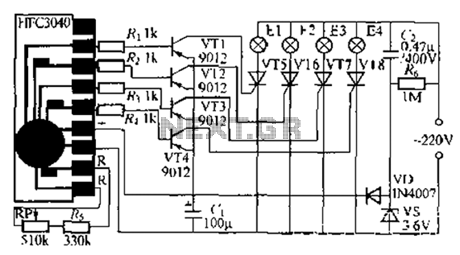
The circuit utilizes a four-way slowly dimming LED driver integrated with iU shoe production and a Qis four flashing lights string controller. The C3484 manifold is specifically designed to operate Ji lights with four lights that flash and slowly...
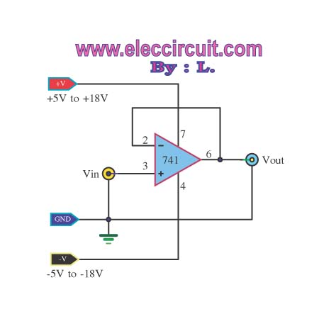
The buffer operational amplifier (op-amp) circuit is utilized for coupling two circuits together. It functions as a unity gain follower, also known as a voltage follower, which is employed to transfer or replicate a voltage from one circuit to...
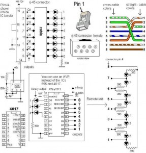
A LAN tester circuit diagram is presented in two designs. The first design utilizes a timer IC 555 and a decade counter 4017. The second design employs a microcontroller ATtiny2313. The first design of the LAN tester circuit incorporates the...
The wireless FM transmitter circuit described here includes an additional RF power amplifier stage following the oscillator stage, which increases the power output to 200-250 mW. The wireless FM transmitter circuit functions by modulating audio signals onto a radio frequency...

The utility vehicle anti-theft alarm circuit consists primarily of two main components essential for its operation. The security circuit is activated when the vehicle owner departs from the vehicle, utilizing an anti-theft switch (S B) to engage the alarm...
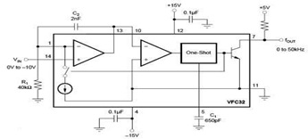
The circuit diagram of a voltage-to-frequency (V/F) converter is presented, designed to handle negative input voltage. It employs the VFC32 voltage-to-frequency converter, which is commonly utilized in various applications. The V/F converter circuit is essential in converting an analog voltage...
Warning: include(partials/cookie-banner.php): Failed to open stream: Permission denied in /var/www/html/nextgr/view-circuit.php on line 713
Warning: include(): Failed opening 'partials/cookie-banner.php' for inclusion (include_path='.:/usr/share/php') in /var/www/html/nextgr/view-circuit.php on line 713