
555 timer compo entry 2
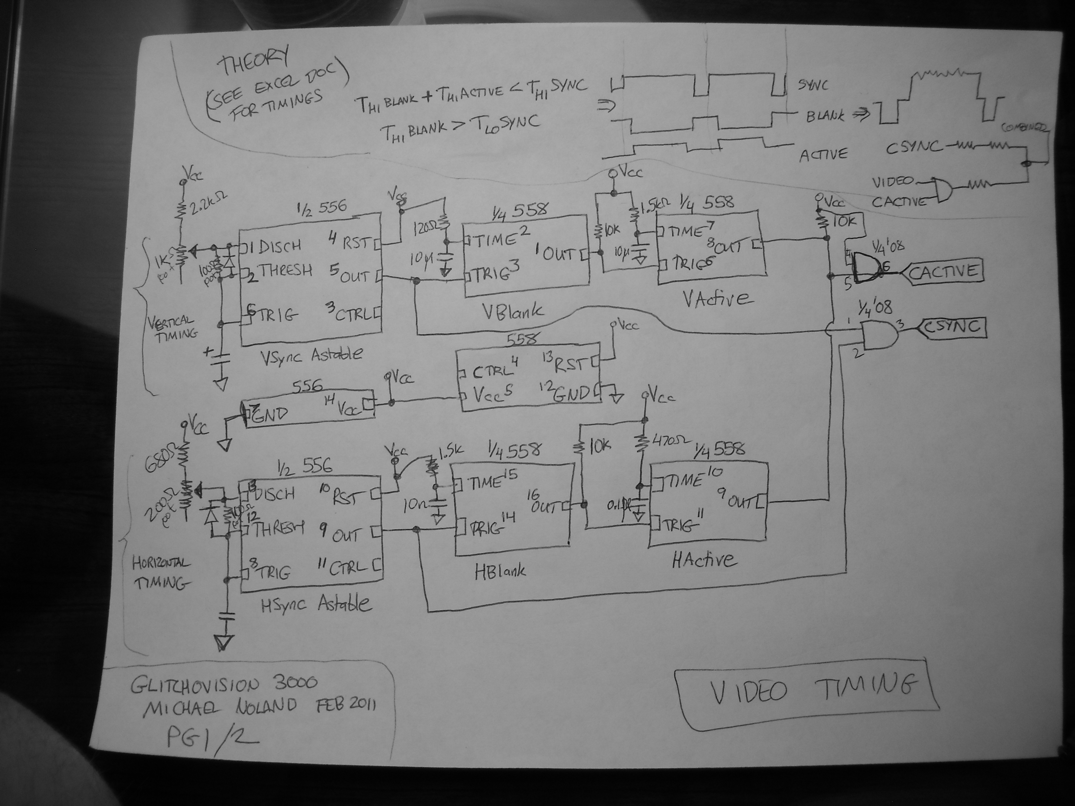
Note 1: Incorporating a reset switch in place of relying on power sequencing during startup is a beneficial enhancement. This feature was not present in the prototype shown in the video, but it is included in the schematic as a dashed box. It would also allow for a "tap to the rhythm" reset, though it would not halt later stages in the same way a reset on a 4017 would.
Note 2 and 3: Adding a pair of diodes could help maintain the control voltage range between approximately 0.7 to 4.3 volts, or using fixed-value resistors may prevent issues when the control voltage deviates significantly.
Note 4: The additional 558 timer on the lid board remains unused. It is partially wired but not integrated into the countdown of the primary 558 sequencer due to time constraints that prevented the wiring of the remaining four switches and potentiometers.
Note 5: Utilizing the opposite ends of the sequencer potentiometers as part of the timing circuit for another 558 timer, which counts down after being triggered on vertical blanking, could provide a visual representation of the notes. This would require relocating the switches to follow the potentiometers.
The design integrates complex timing and sequencing functions for audio synthesis and video output, showcasing the versatility of the 558 and 556 timer ICs in creative electronic applications. The approach allows for significant customization and expansion, making it suitable for experimental audio-visual projects.This entry is a 4 step sequencer controlling an `Atari Punk` synth with a greyscale NTSC video visualization of the output audio, built using two 558 quad-timers and two 556 dual-timers. Sorry in advance for the poor video quality, I will try to get a direct capture next week when I get back from GDC, but I was in a rush to make the contest deadli
ne. Soldering up all those potentiometers, switches, etc. takes a suprising amount of time. These signals are low for the time specified in the RS170 standard (3 lines for vsync, 10. 9 us for hsync), although the final result isn`t exactly up to RS170 spec. It generates a `combined` or industrial sync (which works on every TV I`ve ever tested), but RS170 requires serrating and equalizing pulses to be generated during vsync to prevent 1950s hsync oscillators from losing tracking. Each blanking signal is fed into a 558 monostable timer, which generates the blanking signal (lasting longer than the sync signal and delaying until the image is about past the overscan).
The two sync signals are combined with one AND gate into a CSYNC signal and the two active signals are combined (with wired AND from the 558 open-collector outputs, but buffered into another AND gate) to generate a CACTIVE signal. One 558 quad timer serves as a 4 step sequencer, similar to a traditional use of a 4017 decade counter.
All four steps use the same timing components, but the overall step rate is controlled by varying the control voltage for the 558 timer. You can chain several 558`s together to get longer sequence lengths, but I only ended up wiring switches and pots for 4 steps.
The output of the sequencer is combined with the `left` potentiometer of an atari punk synth implemented in the other 556 (conflating the two for the timing of the astable portion of the synth). The monostable portion of the Atari punk is bog standard, triggered by the astable portion. The audio output is line conditioned and output, as well as being ANDed with the CACTIVE signal and merged with CACTIVE via some mixing pots to generate a final video signal.
Listen and see that atonal goodness. Note 1: Adding a reset switch instead of relying on power-sequencing during startup seems like a solid addition. I didn`t have it in the prototype shown in the video, so it`s listed in the schematic in a dashed box.
It would also provide a nice `tap to the rythm` reset, although it wouldn`t stop the later stages from playing like a reset on a 4017 would. Note 2, 3: Adding a pair of diodes here to keep the range of CV to ~0. 7 to 4. 3 V, or even some fixed value resistors should help prevent nastyness when the control voltage is taken too far out of whack.
Note 4: The other 558 in the lid board isn`t used. It`s partially wired up, but it`s not tied into the countdown of the main 558 sequencer, as I didn`t have time to wire up the other 4 switches and pots. Note 5: Using the opposite end of the sequencer potentiometers as part of the timing circuit for another 558 counting verticallly downwards after triggering on vblank (and wired-ANDing the outputs from them with the output of the sequencer 558) should provide a visual indication of what the notes are (will need to move the switches to after the potentiometers).
🔗 External reference
Related Circuits
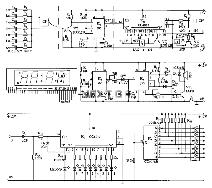
This circuit is primarily designed as a timely reminder system for monitoring individuals on duty who may fall asleep. It features a detection circuit that processes minute signals. As the LED digital electronic timing clock displays the minute, the...
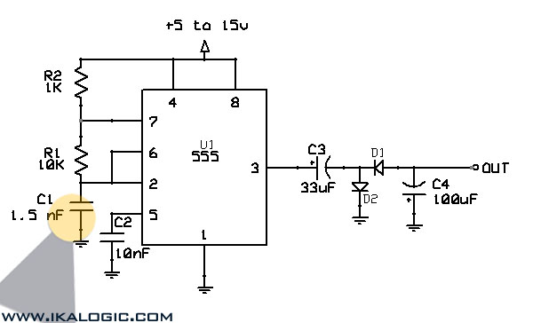
This circuit converts a positive voltage to a negative voltage, resulting in a loss of approximately 1.5 V. For instance, supplying 9 V to the circuit yields an output of -7.5 V. Additionally, this circuit can function as a...
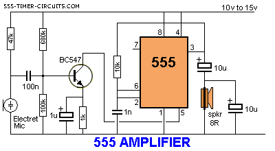
The 555 timer can function as an amplifier, operating similarly to pulse-width modulation. The component values lead the 555 to oscillate at approximately 66 kHz, a frequency to which the speaker does not respond. Instead, the speaker reacts to...
The circuit consists of two synchronized multivibrators formed by a pair of 555 timer circuits. It is capable of generating two synchronized pulse signals, with the spacing and frequency adjustable by modifying the time constant. The circuit offers flexibility...
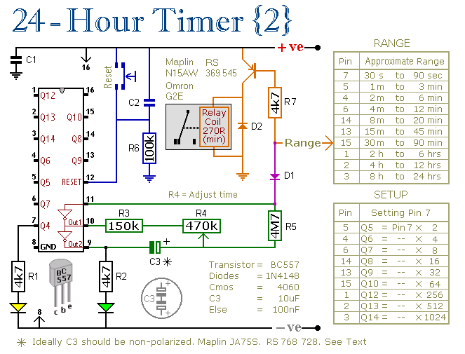
These two circuits are multi-range timers that offer periods of up to 24 hours and beyond. They can function as repeating timers or single-shot timers. Both circuits are fundamentally the same, with the primary distinction being their behavior in...
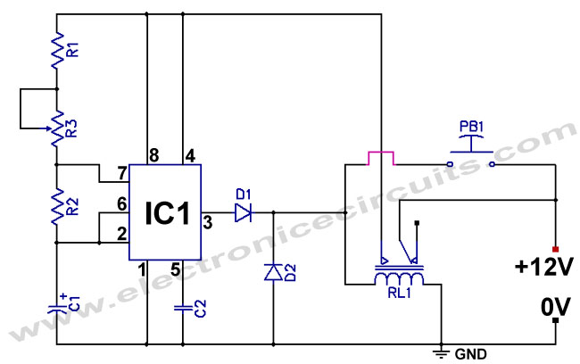
The standard 555 timer circuit consumes power from the battery even when the start push-button (PB1) is not pressed, due to a potential divider created by three 5kΩ resistors within the integrated circuit (IC). This power consumption, referred to...