
555 Anti-night sleep control circuit diagram recorder
The circuit can be divided into several key components, each playing a vital role in its functionality. The timing mechanism is central to the operation, utilizing a 555 timer configured in monostable mode. This setup allows the circuit to create a precise timing interval, ensuring that the reminder system activates accurately. The choice of resistors and capacitors (R10 and C8) is critical, as they define the timing characteristics of the monostable circuit, allowing for flexibility in adjusting the reminder intervals.
The counting mechanism, implemented with IC2, is essential for tracking the elapsed time. This IC provides the ability to count pulses and, when reaching the designated threshold, activates the corresponding output to trigger the alarm system. The integration of transistors (VT1, VT2, VT3) enhances the circuit's capability to handle varying voltage levels and control higher power devices such as relays.
The alarm system is designed to produce a sound that can effectively awaken an individual, utilizing a speaker driven by a power amplifier (3AD5). The varying tones generated by the modulation of the multivibrator (IC6) ensure that the alarm is not only loud but also attention-grabbing, which is crucial for its intended purpose.
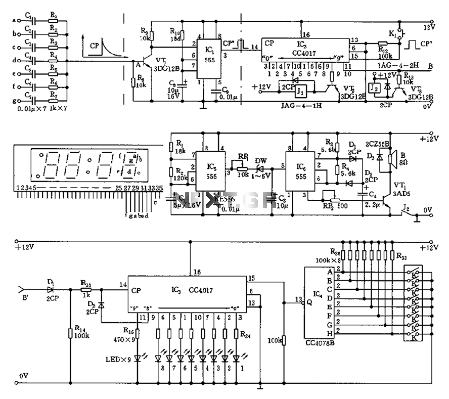
Overall, this timely reminder circuit is a sophisticated assembly of components working in harmony to provide an effective solution for monitoring individuals on duty, ensuring they remain alert and attentive during their responsibilities. The design emphasizes reliability, accuracy, and user-friendliness, making it a valuable addition to any supervisory environment. As shown, this circuit is mainly used in a timely reminder dozing who can supervise and the number of records on duty were asleep. Figure d detection circuit is a minute signal . When the LED digital electronic timing clock minute display character change over time, Figure c strokes a ~ g end there will be at least a change. The detection of the use of minute pulses from IC2 form a time recording and alarm circuit for duty to remind supervision.
Since the display minute of seven (a ~ g) at the same time with a couple of strokes may change, so remove the minute pulses may have several. Monostable delay circuit 555 and R10, C8 and other components, it needs to receive one pulse per minute, that the timing of time 10 seconds remaining stroke pulse does not work.
Monostable timing circuit width by R10 and C8 time constant to decide. VT1 for the inverting amplifier stage, negative pulse is applied to the trigger terminal 2 feet, flip the circuit 555 outputs a shaped pulse CP. IC2 is a decimal counting/distributor, longest timing of 9 minutes. When the count to the first nine pulse, which is the cumulative timer to 9 minutes, was 9 feet high potential, VT2 conduction, relay, Fig.
B sounder power is turned on, a timely caution attendant press the reset switch K1, the count circuit is reset, time to start again. If you do not press the switch K1,1 minutes after that accumulated to the first 10 minutes, was 11 feet high potential, VT3 conduction, the relay K2 pull, the power diagram e alarm circuit is turned sharp and intermittent alarm sound sleepy attendant will wake up and timely press reset switch K1.
11-pin output of IC2 is also added to the diagram of f IC3 14 feet, so that the timer circuit was three feet high potential, LED1 light. Thus, if the over-nine 10 minutes, 9 feet IC3 also showed high potential, LED9 red light, indicating sleepy attendant has up to 9 times.
Noting 9 feet by D2 connected to IC3 end of CP, 9 feet high has been described timing circuit CP end sealed, no record, but LED1 ~ LED9 luminescence will remain for future reference. Figure f cleared the right of the display circuit. IC5 is a diagram of a typical e multivibrator, the frequency of the oscillation parameters shown about 4Hz square wave around, the RP1, DW, after C3 buck smooth acceleration to IC6 control terminal 5 feet of IC6 multivibrator modulated, so that given a change of tone acoustic signal, power amplification by 3AD5 promote 10W speaker, issued a deafening alarm signal varying tones.
Related Circuits
High-voltage isolation switches must not be connected to loads that could create an arc, which may lead to a short circuit between the high-voltage bus and result in accidents that endanger both equipment and personnel safety. Consequently, high-voltage switchgear...
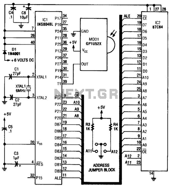
This circuit is based on the Sharp GP1U52X infrared module and the 1NS8048L microprocessor. The GP1U52X is a hybrid integrated circuit and infrared detector that provides a strong, clean signal for subsequent filtering and demodulation. The circuit utilizes the Sharp...
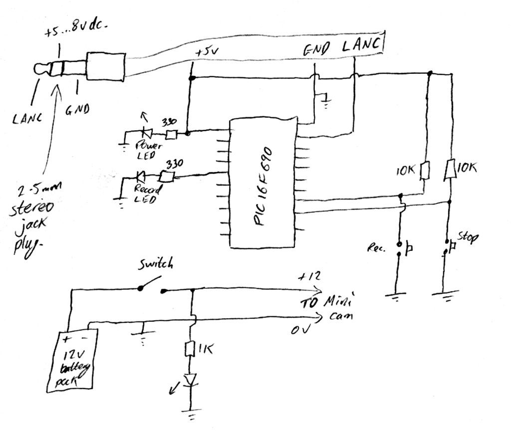
Inexpensive PIC-controlled helmet camera utilizing Sony LANC, suitable for extreme sports. This guide will demonstrate how to create an affordable helmet camera. The proposed electronic schematic involves a PIC microcontroller interfaced with a Sony LANC (Local Application Control Bus) to...
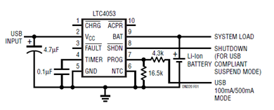
The schematic presented illustrates a minimal component solution for a USB battery charger utilizing the LTC4053 integrated circuit (IC) to create a fully compliant USB charger. This IC functions as a standalone linear charger designed for lithium-ion (Li-ion) batteries,...
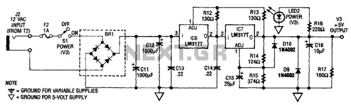
The power supply presented is intended to function with a wall transformer. This circuit can be utilized alongside a variable supply for testing circuits in a laboratory setting. T2 serves as a 12-V wall transformer. The power supply circuit is...
The locator utilizes a transistor radio as the detector. By tuning the radio to a weak station, the capacitor C1 can be adjusted so that the locator's oscillator beats against the received signal. When the search head passes over...