
555 timer ic based simple servo

The servo control circuit utilizes a 555 timer in astable mode to generate the required pulse-width modulation (PWM) signals. The 555 timer is configured with resistors and capacitors to establish the frequency and duty cycle. The output from the timer is connected to the control pin of the servo, which interprets the duration of the pulse to determine its position.
In practice, the circuit can be enhanced by incorporating additional components such as a potentiometer to allow for manual adjustment of the pulse width, thereby providing a means to control the servo position dynamically. Furthermore, a microcontroller can be integrated into the design for more complex control schemes, enabling the implementation of feedback systems or multiple servo control through programming.
When constructing the power supply for the servos, a regulated supply capable of delivering the required current is essential. A common approach is to use a switching power supply or a battery pack that can handle the peak current demands of the servos during operation. It is advisable to include decoupling capacitors near the servo power connections to mitigate voltage spikes and ensure stable operation.
In summary, the servo control circuit is a fundamental building block for various electronic projects, providing precise control over mechanical movements through simple yet effective PWM techniques. Proper design considerations regarding power supply and component selection will enhance the reliability and performance of the servo system.Servos became valuable products for any variety of plans, like robotics, automation or only remotely controlling some thing, for example model vehicle steering. They`re reasonably low-priced and also simple to have hold of, however controlling them can be a little challenging while they requrie specific moment to control the output to advance into
a preferred position. Almost all servos use a 50Hz refresh rate (20ms) for level a beat of among 1 and 2ms is required to control the output to advance among -45degrees and +45degrees. The circuit is quite self instructive. We start using a 555 timer IC to build the pulse each 20ms which has a responsibility cycle of among 5 and 10% (1-2ms).
All of the components employed are common components. You are able to drive several servos with the identical signal by using circuit to all or any have same output or create multiple driver circuits to control several servos to various outputs. Also be aware that servos require much current when commanding them also to maintain a location below load, this is around several amps!
And so make notice of the while creating your electrical power supply. 🔗 External reference
Related Circuits
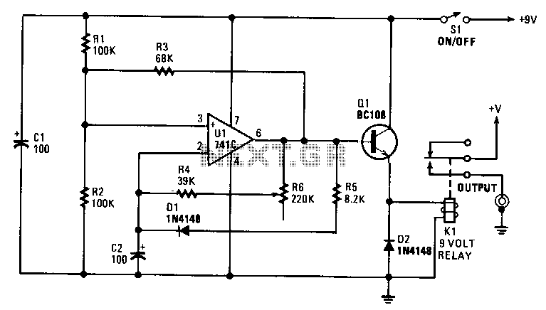
The interval can be set between approximately 5 to 30 seconds. A relay controls the slide-change mechanism. Operational amplifier U1 functions as a type of Schmitt trigger. Resistors R1 and R2 bias the non-inverting input at pin 3 of...
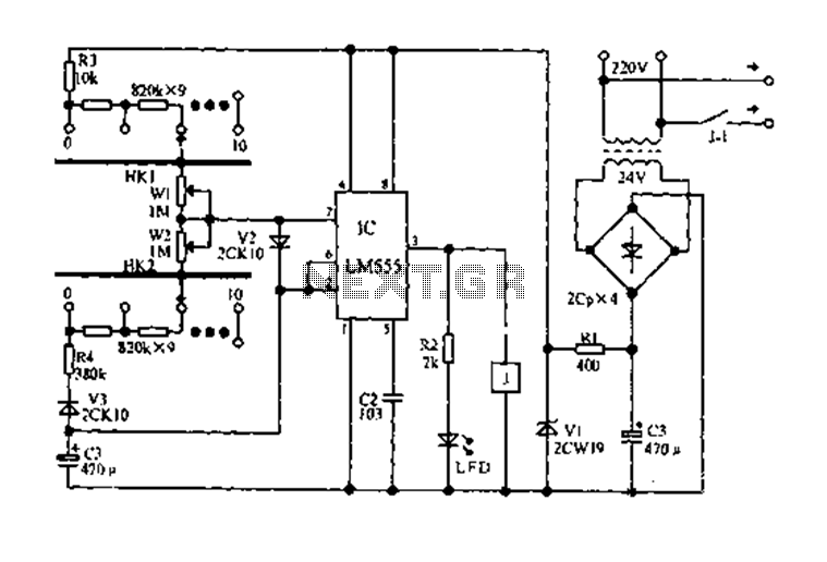
The circuit diagram for an electric start and stop timer is illustrated in the following cycle. It utilizes the LM555 integrated circuit configured as an adjustable duty cycle multivibrator. The circuit includes components C3, KH1, W1, KH2, and W2,...
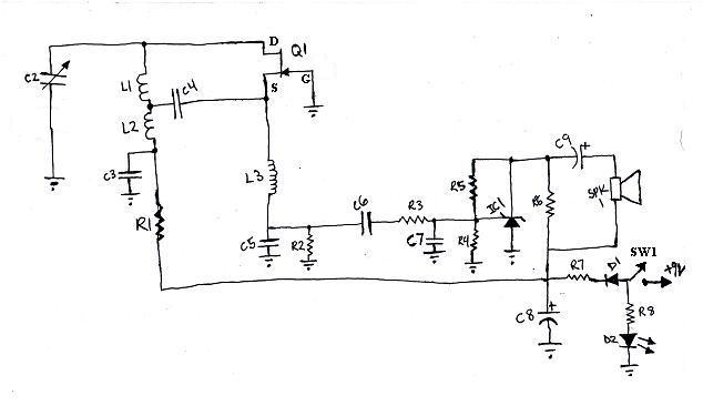
L1 and L2 were constructed by wrapping three tight loops side by side around a Sharpie marker. L2 was additionally created by wrapping approximately 8 inches of 35 AWG magnet wire around a ferrite core, ensuring that the windings...
The circuit diagram of this programmable sequencer can be utilized for various timing applications. An audible tone is generated before the start of each interval, while a seven-segment LED display indicates the current interval number. A buzzer sounds again...
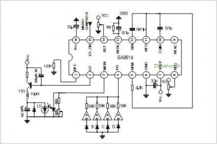
The SA9618A is designed for ALPC and signal conversion between a CD optical pickup and a decoding chip. This integrated circuit (IC) features an interconnection for a general CD optical pickup photodiode bias voltage VREF generation circuit, an RF...
The electronic switch consists of the CK-4 type magnetic control switch and the components VT1, R1, and R2. When the bathroom door is closed, the permanent magnet ZT and the reed switch GA come into proximity, which separates the...