
simple home made fm radio receiver

The circuit utilizes two inductors, L1 and L2, which serve critical roles in filtering and impedance matching within the RF circuitry. L1, formed by tightly wrapping the wire around a cylindrical object, achieves a specific inductance value that is essential for the desired performance characteristics. The choice of a Sharpie marker as a former provides a convenient and consistent diameter, yielding predictable inductance based on the number of turns and the wire gauge used.
L2, on the other hand, is constructed using a ferrite core, which enhances the magnetic coupling of the inductor and improves its efficiency at high frequencies. The selection of 35 AWG magnet wire is significant due to its thin diameter, allowing for more turns to be wound in a limited space, thus increasing the inductance without significantly increasing the physical size of the component. The use of hot glue ensures that the windings remain stable and do not shift during operation, which is crucial for maintaining the inductance value.
For applications where custom inductors are not feasible, utilizing commercially available RF chokes within the specified range of 20 to 30 microhenries is a practical alternative. These components are designed for high-frequency applications and are readily available, simplifying the design process while ensuring reliable performance. The overall design should take into consideration the specific requirements of the application, including operating frequency, current handling, and physical space constraints.L1 and L2 were made by wrapping three tight side by side loops around a sharpie marker, I also made L2 by wrapping about 8 inches of 35AWG magnet wire around a ferrite core, careful to make the windings side by side and glued it in place with a hot glue gun, you can use any 20-30 uH RF choke though, you don`t have to make your own. 🔗 External reference
Related Circuits
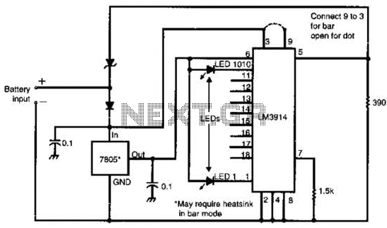
Many amateur receivers are equipped with an S meter that does not operate logarithmically. The proposed circuit is intended to enhance such receivers. Although integrated circuits like the CA3089 or CA3189 are not commonly used today, they play a...
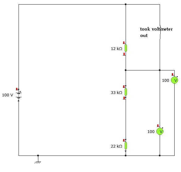
A user is utilizing YENKA software to diagram circuits but is experiencing confusion regarding the voltage calculations in a basic series circuit, as illustrated in the attached image. In a basic series circuit, components are connected end-to-end, forming a single...
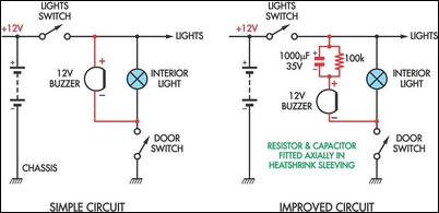
These two headlight reminder circuits are easy to install and operate on the KISS (Keep It Simple Stupid) principle. The simple circuit involves adding a 12V piezo buzzer between the lights circuit and a door switch. The buzzer sounds...
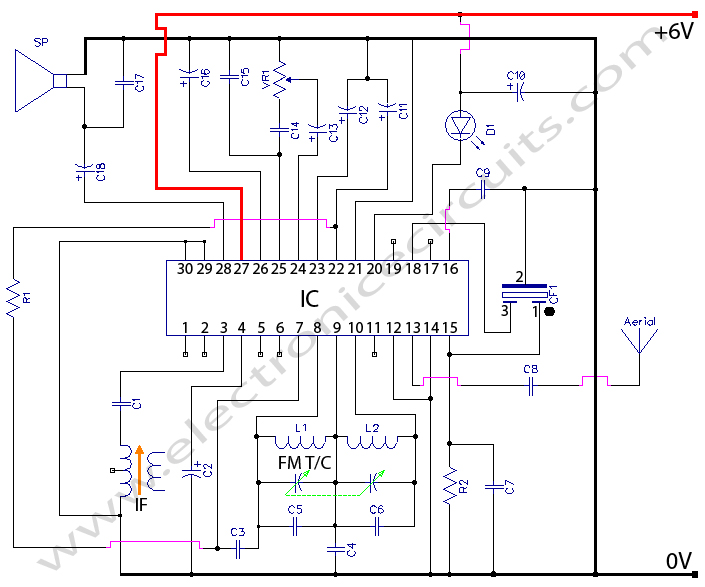
CXA1019 FM RADIO CXA1019 is a one-chip FM/AM radio IC designed for radio-cassette tape recorders and headphone tape recorders, and CXA1019S has the... The CXA1019 is an integrated circuit (IC) specifically engineered for FM/AM radio applications, particularly within radio-cassette tape...
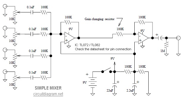
This is a simple mixer featuring four inputs and two operational amplifiers (op-amps). It is designed for mixing microphones or effects outputs. The overall gain from input to output is unity when the potentiometer associated with the input is...
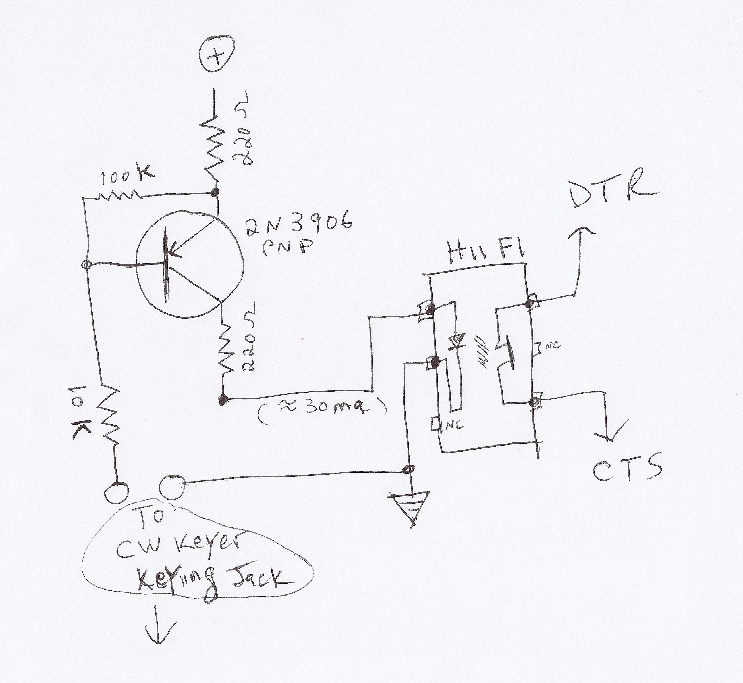
This video demonstrates how to initiate multiple instances of QsoNet's Dahdidah CW Software Keyer using FABULATECH's Virtual Serial Port Splitter. Four separate... The QsoNet Dahdidah CW Software Keyer is a sophisticated tool designed for amateur radio operators, allowing them to...