
555 timer IC

In monostable mode, the 555 operates as a "one-shot" pulse generator, suitable for applications like timers, missing pulse detection, bounce-free switches, touch switches, frequency dividers, capacitance measurement, and pulse-width modulation (PWM). In astable mode, the 555 functions as an oscillator, applicable in LED flashers, pulse generation, logic clocks, tone generation, and security alarms. By selecting a thermistor as the timing resistor, the 555 can be utilized in temperature sensing applications, where the output pulse period correlates with temperature. A microprocessor-based circuit can then interpret the pulse period to determine temperature, enabling linearization and calibration. In bistable mode, or as a Schmitt trigger, the 555 can function as a flip-flop when the DIS pin is not connected and no capacitor is used, which is useful for bounce-free latched switches.
In monostable mode, the 555 timer generates a pulse when it receives a trigger signal at the input, dropping below one-third of the supply voltage. The pulse width is determined by an RC network comprising a capacitor (C) and a resistor (R). The pulse concludes when the capacitor voltage reaches 2/3 of the supply voltage. The output pulse width can be adjusted by varying the values of R and C to meet specific application requirements. A noted disadvantage of using the timer IC in monostable mode is that the time interval between triggering pulses must exceed the RC time constant. In bistable mode, the 555 timer acts as a basic flip-flop, with trigger and reset inputs (pins 2 and 4) held high via a pull-up resistor.The 555 timer IC is an integrated circuit (chip) used in a variety of timer, pulse generation and oscillator applications. The part is still in widespread use, thanks to its ease of use, low price and good stability. As of 2003 [update], it is estimated that 1 billion units are manufactured every year. [1] The IC design was proposed in 1970 by H ans R. Camenzind and Jim Ball. After prototyping, the design was ported to the Monochip analogue array, incorporating detailed design by Wayne Foletta and others from Qualidyne Semiconductors. Signetics (later acquired by Philips ) took over the design and production, and released the first 555s in 1971.
Depending on the manufacturer, the standard 555 package includes over 20 transistors, 2 diodes and 15 resistors on a silicon chip installed in an 8-pin mini dual-in-line package (DIP-8). [2] Variants available include the 556 (a 14-pin DIP combining two 555s on one chip), and the 558 (a 16-pin DIP combining four slightly modified 555s with DIS & THR connected internally, and TR is falling edge sensitive instead of level sensitive).
The NE555 parts were commercial temperature range, 0 °C to +70 °C, and the SE555 part number designated the military temperature range, ’55 °C to +125 °C. These were available in both high-reliability metal can (T package) and inexpensive epoxy plastic (V package) packages.
Thus the full part numbers were NE555V, NE555T, SE555V, and SE555T. It has been hypothesized that the 555 got its name from the three 5 k © resistors used within, [3] but Hans Camenzind has stated that the number was arbitrary. [1] Low-power versions of the 555 are also available, such as the 7555 and CMOS TLC555. [4] The 7555 is designed to cause less supply glitching than the classic 555 and the manufacturer claims that it usually does not require a "control" capacitor and in many cases does not require a decoupling capacitor on the power supply.
Such a practice should nevertheless be avoided, because noise produced by the timer or variation in power supply voltage might interfere with other parts of a circuit or influence its threshold voltages. Monostable mode: in this mode, the 555 functions as a "one-shot" pulse generator. Applications include timers, missing pulse detection, bouncefree switches, touch switches, frequency divider, capacitance measurement, pulse-width modulation (PWM) and so on.
Astable free running mode: the 555 can operate as an oscillator. Uses include LED and lamp flashers, pulse generation, logic clocks, tone generation, security alarms, pulse position modulation and so on. Selecting a thermistor as timing resistor allows the use of the 555 in a temperature sensor: the period of the output pulse is determined by the temperature.
The use of a microprocessor based circuit can then convert the pulse period to temperature, linearize it and even provide calibration means. Bistable mode or Schmitt trigger : the 555 can operate as a flip-flop, if the DIS pin is not connected and no capacitor is used.
Uses include bounce free latched switches. In the monostable mode, the 555 timer acts as a one-shot pulse generator. The pulse begins when the 555 timer receives a signal at the trigger input that falls below a third of the voltage supply. The width of the output pulse is determined by the time constant of an RC network, which consists of a capacitor (C) and a resistor (R).
The output pulse ends when the voltage on the capacitor equals 2/3 of the supply voltage. The output pulse width can be lengthened or shortened to the need of the specific application by adjusting the values of R and C. [5] While using the timer ic as a monostable the main disadvantage is that the time span between the two triggering pulses must be greater than the RC time constant.
In bistable mode, the 555 timer acts as a basic flip-flop. The trigger and reset inputs (pins 2 and 4 respectively on a 555) are held high via Pull-up resistor 🔗 External reference
Related Circuits
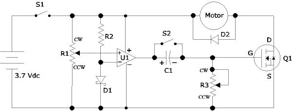
The following circuit illustrates an Airplane Flight Timer Circuit Diagram. Features include switches in the closed position and battery voltage maintained at a safe level. The Airplane Flight Timer Circuit is designed to provide a reliable timing mechanism for monitoring...
The cumulative timer circuit comprises resistor R1 and an internal crystal oscillator, represented in a chart. Resistors R1 and R2 are metal film types, while resistors R3 to R5 are rated at 1/8W and also of the metal film...
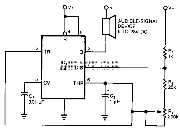
The simple circuit converts the continuous beep of an audible-signal device, such as a Mallory sonalert, into a unique warble or chirp. The values of resistor R and capacitor C2 determine the specific tone quality produced. With a 1kΩ...
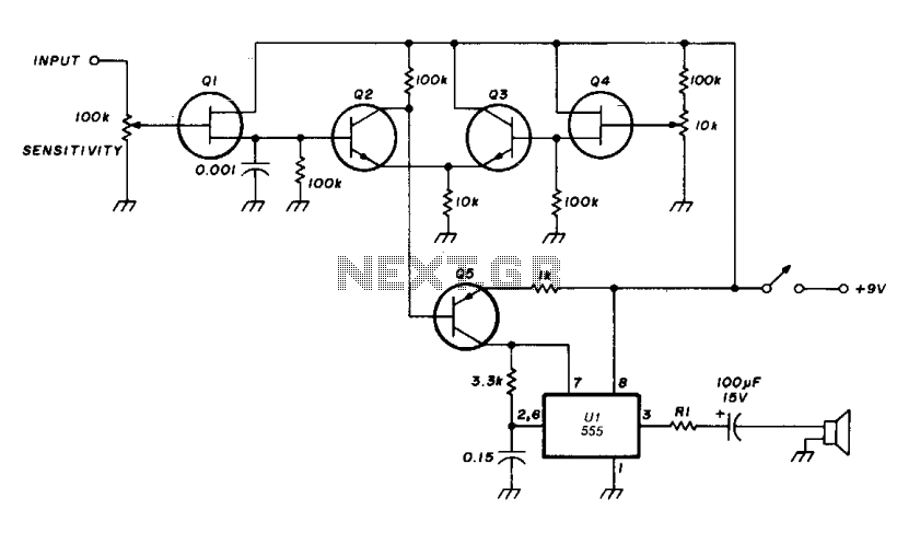
The transistor Q5 and the 1000-ohm resistor form the variable element necessary for controlling the frequency of the voltage-controlled oscillator (VCO) by limiting the charging current flowing into the 0.15 microfarad timing capacitor based on the forward bias applied...
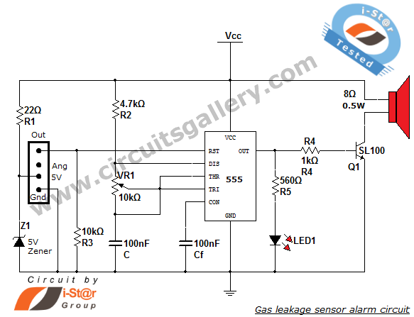
This article discusses a home security alarm circuit designed to detect LPG gas leakage. The circuit utilizes a gas sensor module, SEN 1327, which incorporates a QM 6 gas sensor. The output signal from this gas sensor module is...
The circuit consists of four light-controlled electronic switches, timing circuits, voice circuits, audio circuits, and other components. It is designed to celebrate birthdays or similar occasions, with features such as birthday candles that can be lit or extinguished. The...