
Cumulative timer circuit diagram
The cumulative timer circuit operates by utilizing a combination of resistors, capacitors, and diodes to create a timing function. Resistor R1 serves as the primary timing resistor, influencing the charge and discharge cycles of the capacitor C, which determines the timing intervals. The choice of metal film resistors for R1, R2, R3, R4, and R5 is significant due to their stability and precision, which are essential for accurate timing applications.
The internal crystal oscillator, characterized by its stable frequency output, provides a reliable clock signal to the circuit, ensuring that timing is consistent over extended periods. The capacitor C, being an aluminum electrolytic type, is selected for its ability to handle voltages exceeding 10V, which is crucial for applications where higher voltage levels may be encountered.
The diodes VD1 to VD4, specifically the 1N4007 rectifiers, are employed for their robustness in handling reverse voltage and ensuring proper rectification in the circuit. These diodes facilitate the conversion of alternating current (AC) to direct current (DC), which is necessary for the functioning of the timer circuit. The additional diode VD5 may be used for protection or as part of a more complex timing mechanism, depending on the specific design requirements.
In summary, this cumulative timer circuit is designed for precision timing applications, utilizing high-quality components to ensure reliability and accuracy. The combination of resistors, capacitors, and diodes forms a well-structured timing mechanism suitable for various electronic applications.The cumulative timer circuit consists of resistor R1 and spreadsheet internal crystal oscillator BC, and it is shown as the chart. R1 and R2 choose the metal film resistors: R3 ~ R5 select the 1/8W metal film resistors. C select the aluminum electrolytic capacitor with voltage being above 10V. VD1 ~ VD4 use the 1N4007 silicon rectifier diodes; VD5 uses the 1.. 🔗 External reference
Related Circuits
The SE555/NE555 timer was first introduced by the Signetics Corporation around 1971. Pin connections and functions are as follows: Pin 1 (Ground) - This pin serves as the ground or common pin, representing the most negative supply potential of...
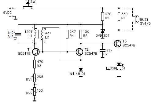
This metal detector circuit project is a simple design based on common electronic components. It utilizes transistors to provide a visual indication through an LED and an acoustic signal to alert users when metal is detected. To calibrate the...
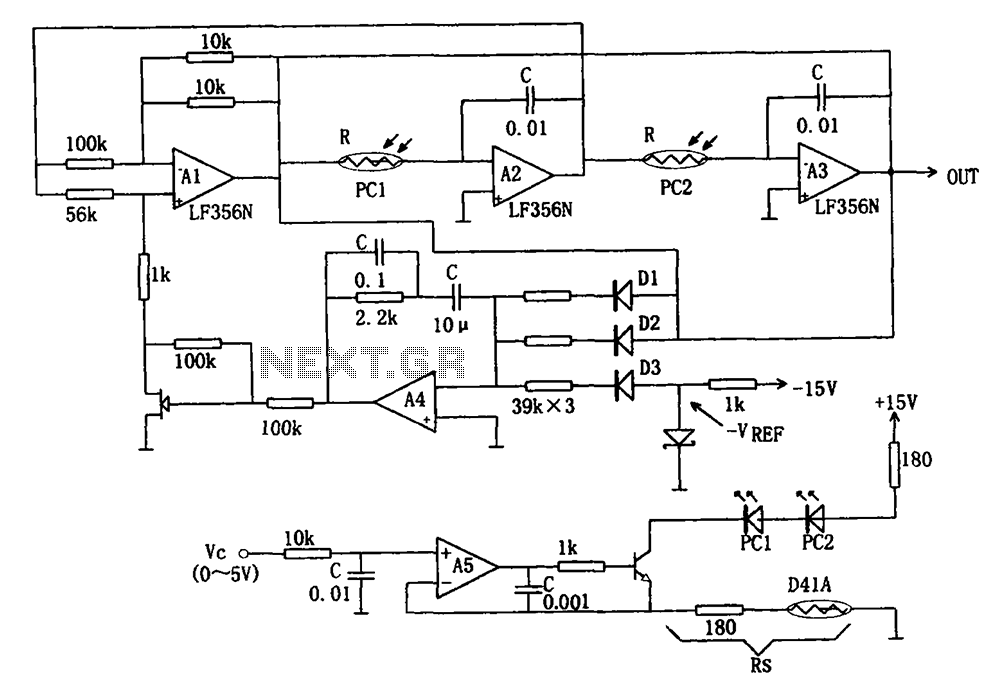
The wideband sinusoidal voltage-controlled oscillator circuit is designed such that the oscillation frequency is determined by an integrating resistor R and a capacitor C. The voltage-controlled oscillator is constituted by the applied control voltage Vc and a control resistor...
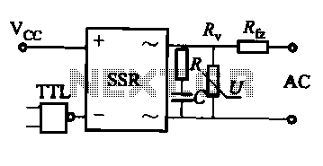
This document discusses the AC solid-state relay (AC-SSR) and presents its basic application circuit as illustrated in Figure (a). Additionally, it includes a TTL drive SSR circuit depicted in Figure (b), a CMOS driver circuit for the SSR shown...
The LM317T is an adjustable three-terminal positive voltage regulator that can supply over 1.5 amps with an output voltage range of 1.25 to 37 volts. It features built-in current limiting and thermal shutdown, making it highly reliable and resistant...
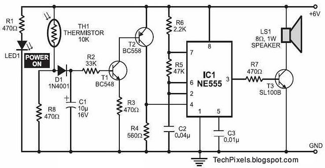
The following circuit illustrates a fire alarm circuit diagram utilizing the NE555 integrated circuit (IC). Features include functioning as a heat sensor and incorporating a 10 kilo-ohm resistor. The fire alarm circuit based on the NE555 IC is designed to...