
555 Timer IC For RF Sweeper
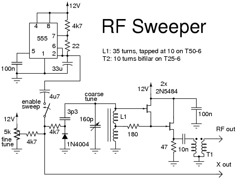
The circuit utilizes the 555 Timer IC, configured in astable mode, to generate a continuous square wave output. This output can be adjusted to sweep through a range of frequencies, making it suitable for RF applications such as signal scanning or interference testing. The 1N4004 diode serves as a protective component, preventing reverse voltage spikes that could damage the timer IC or other components in the circuit.
The JF1OZL, a specific type of RF oscillator, is integrated into the design to enhance the frequency tuning capabilities. A potentiometer is included in the circuit, allowing for fine adjustments to the frequency output. This feature is particularly useful in RF applications where precise frequency control is essential for effective operation.
The overall design emphasizes stability and reliability, with the 555 Timer providing a robust solution for generating the desired RF signals. The combination of the timer IC, diode, and potentiometer creates a versatile circuit capable of meeting various RF sweeping requirements. Proper layout and component selection will ensure optimal performance and longevity of the circuit in practical applications.The following circuit shows about 555 Timer IC For RF Sweeper. Features: used a 1N4004 Diode, JF1OZL uses a pot for a fine frequency control .. 🔗 External reference
Related Circuits
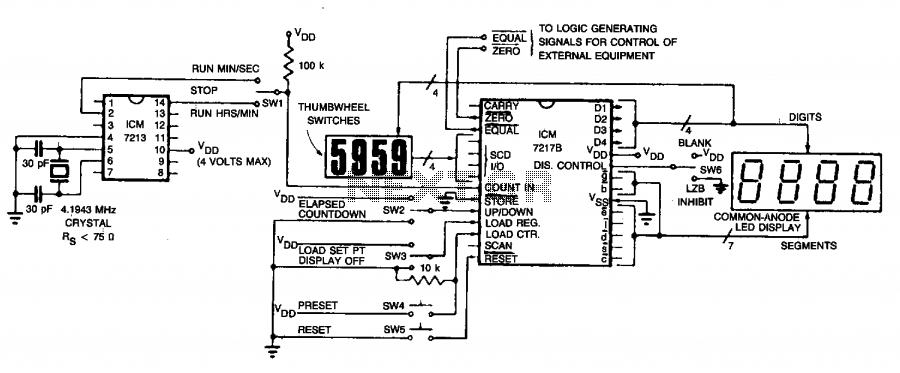
The circuit employs an ICM7213 precision timebase generator with a frequency of 4.1943 MHz, which is utilized for generating pulses that are counted by an ICM7217B counter. Thumbwheel switches are incorporated to allow the user to input a starting...
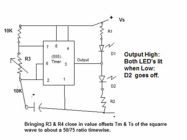
The output signal is configured to go high for approximately 0.5 seconds and then low for around 1.33 seconds. However, there is an issue present. The circuit in question likely employs a timing mechanism to achieve the specified output signal...

The circuit below demonstrates the generation of a single positive pulse that is delayed in relation to the trigger input time. It is similar to a previously described circuit but utilizes two stages, allowing for control over both the...
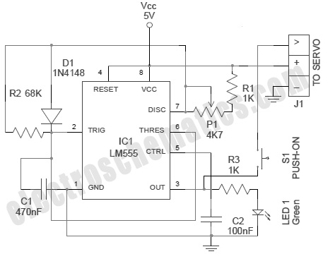
A servo is an error-sensing feedback control mechanism used to correct the performance of a system. A servo motor is a DC motor equipped with a servo mechanism. A servo motor is an electromechanical device that utilizes a closed-loop control...
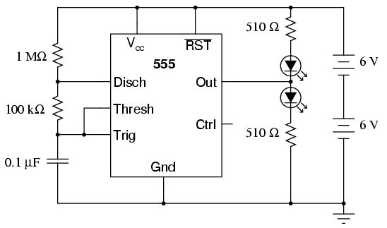
An oscilloscope is useful for analyzing the waveforms produced by this circuit, although it is not essential. An audio detector serves as a valuable piece of test equipment for this experiment, particularly if an oscilloscope is unavailable. The "555"...

This is a Power Pulse Generator Circuit that utilizes the integrated circuit NE555 as a square wave oscillator generator. The frequency can be adjusted by varying resistor R1. The output from the NE555 is then sent to a transistor...