
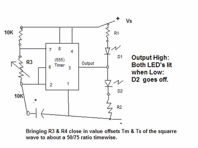
555 timer as a flip-flop
The circuit in question likely employs a timing mechanism to achieve the specified output signal behavior. A common approach to generate such timing sequences is through the use of a 555 timer IC configured in monostable mode.
In this configuration, when a trigger signal is applied to the timer, it produces a high output for a predetermined duration, which in this case is set to 0.5 seconds. The duration of the high output is determined by the values of the resistor (R) and capacitor (C) connected to the timer. The time period (T) can be calculated using the formula T = 1.1 * R * C, where R is in ohms and C is in farads.
After the high output period, the signal goes low for 1.33 seconds. To achieve this, a second timing circuit or a delay mechanism can be integrated. This could be accomplished with another 555 timer in a similar configuration or by using a microcontroller that can easily handle multiple timing sequences.
If a microcontroller is utilized, it can be programmed to set the output pin high for 0.5 seconds and then low for 1.33 seconds using simple timing functions. The microcontroller's versatility allows for easy modifications to the timing parameters without the need for physical component changes.
Additional considerations include ensuring that the power supply voltage levels are appropriate for the components used, as well as implementing debouncing mechanisms if the trigger signal is sourced from a mechanical switch. Proper decoupling capacitors should also be placed near the power supply pins of the ICs to minimize noise and ensure stable operation.
Overall, the circuit design must be carefully analyzed to identify the root cause of the issue affecting the output signal, whether it be incorrect component values, wiring errors, or potential hardware faults.I have it set up so that I get an out put signal that goes High for about 1/2 second, and then goes low for about 1.33 seconds. The problem is that.. 🔗 External reference
Related Circuits
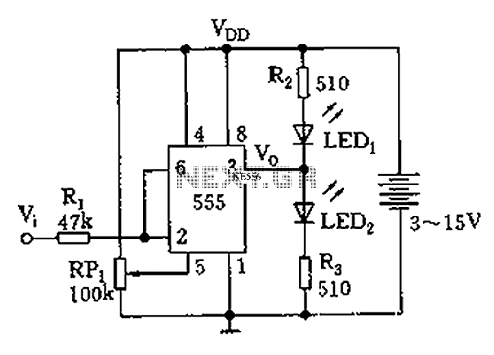
Figure 555 illustrates a simple logic circuit test lead. The test pen utilizes the 555 timer IC as its core component, incorporating a Schmitt trigger to assess the logic state of digital circuits. The circuit has two outputs: when...
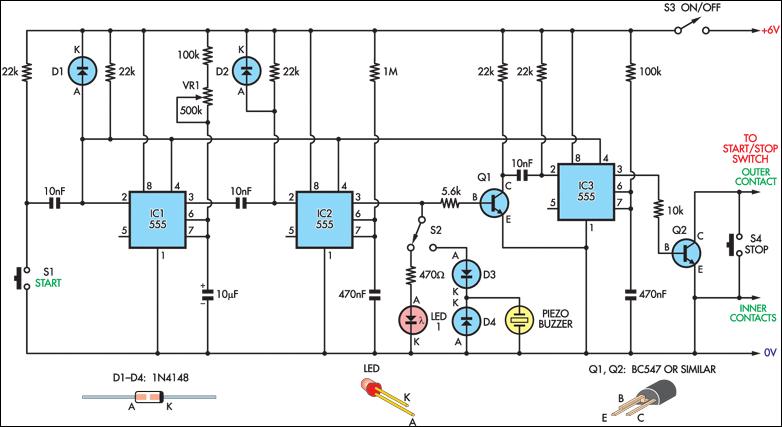
Integrate an inexpensive stopwatch into this circuit to create an accurate reaction timer. The circuit is connected in parallel with the start/stop button of the watch through a 2.5mm socket, which fits securely in one corner of the casing....
The core component of this circuit is the 555 timer IC. The alert sound does not stop immediately when the switch is activated; instead, it ceases automatically after a predetermined time period, which is set by the resistance of...

The following method allows the timer to be triggered by a normally closed switch. This would be useful in applications such as intrusion alarms where the protection circuit is broken if a window or door is opened. Trigger Input...
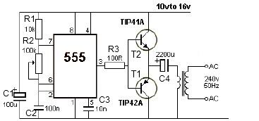
12V power inverter circuit utilizing a 555 timer for an electronic project. The 12V power inverter circuit is designed to convert a DC voltage of 12 volts into an AC voltage suitable for powering small electronic devices. The core component...
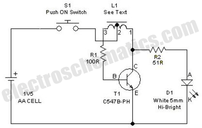
This simple LED driver circuit allows the operation of up to seven LEDs using a single NiMH (Nickel Metal Hydride) AA cell. The circuit generates voltage pulses. The LED driver circuit is designed to efficiently power multiple LEDs while maintaining...
Warning: include(partials/cookie-banner.php): Failed to open stream: Permission denied in /var/www/html/nextgr/view-circuit.php on line 713
Warning: include(): Failed opening 'partials/cookie-banner.php' for inclusion (include_path='.:/usr/share/php') in /var/www/html/nextgr/view-circuit.php on line 713