
555 timer Mono stable (one shot) circuit circuit
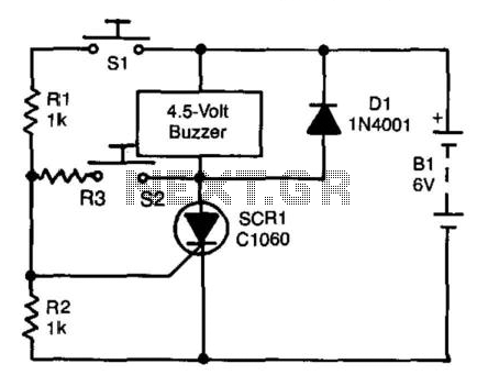
The described circuits utilize the 555 timer in monostable mode, where the timer generates a single output pulse in response to a trigger input. In the first circuit, the push button serves as the trigger, initiating the timing cycle upon being pressed. The timing duration is determined by the resistor-capacitor (RC) network connected to the 555 timer. When the button is pressed, the capacitor begins charging through the resistor, and once the voltage across the capacitor reaches two-thirds of the supply voltage, the output of the timer switches from low to high, activating the relay.
In the second circuit, designed for shorter timing applications, the capacitor is connected in parallel with the push button. This arrangement allows the capacitor to charge quickly when the button is pressed, but it also isolates the timer from the continuous closure of the switch. As a result, the timer only registers the initial transition of the switch from open to closed, effectively ignoring any subsequent state changes while the switch remains closed. This feature is particularly useful in applications where the user might hold down the button for an extended period, as it prevents unintended relay activation beyond the desired timing duration.
Both circuits can be powered by a standard DC power supply compatible with the 555 timer's operating voltage range, typically between 4.5V and 15V. The relay used in conjunction with the timer can be selected based on the load requirements, ensuring it can handle the current and voltage specifications of the intended application. The output of the 555 timer can be connected directly to the relay's coil, with appropriate flyback diode protection to prevent voltage spikes from damaging the timer when the relay is de-energized.
Overall, these circuits provide flexible solutions for controlling relay operations based on user input, with the capability to adjust timing characteristics through the selection of resistor and capacitor values in the timing network.The two circuits illustrate using the 555 timer to close a relay for a predetermined amount of time by pressing a momentary N/O push button. The circuit on the left can be used for long time periods where the push button can be pressed and released before the end of the timing period.
For shorter periods, a capacitor can be used to isolate the switch so that only the initial switch closure is seen by the timer input and the switch can remain closed for an unlimited period without effecting the output.. 🔗 External reference
Related Circuits

This inverter circuit is designed to power electric razors, stroboscopes, flash tubes, and small fluorescent lamps using a 12-volt car battery. Unlike typical feedback oscillator inverters, this design features a separate oscillator from the output stage, allowing for easy...
A self-interrupting device connected to a voltage source operates as a switch that continuously opens and closes; thus, the circuit does not latch in the conventional manner, allowing the alarm to function only while switch SI is closed. Due...
Some relays will become warm if they remain energized for some time. The circuit shown here will actuate the relay as before but then reduce the hold current through the relay coil by about 50%, thus considerably reducing the...
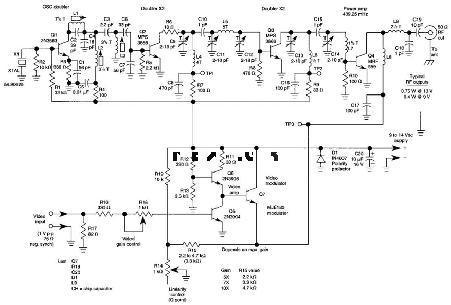
The three schematics illustrate three building blocks for a 10-meter SSB transmitter. These blocks can also be utilized independently as circuit modules for other transmitters. The VFO board incorporates an FET transmission oscillator, with the VFO signal being mixed...
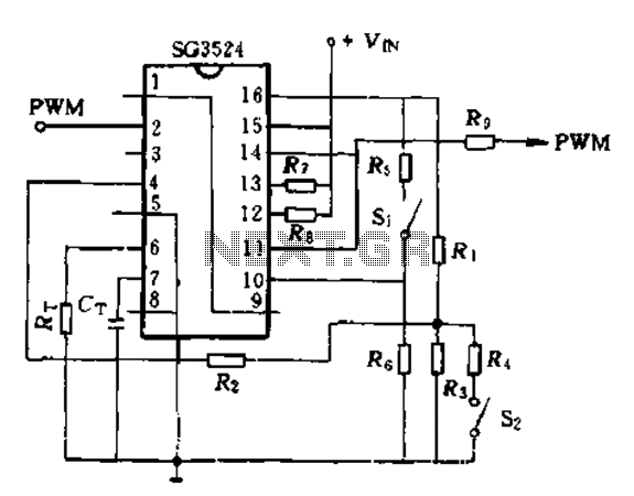
The SG3524 is utilized solely as a pulse width modulator. The error amplifier is configured in a follower arrangement. As illustrated in Figure 10-7, the ACR output connects to PWM output pin 2, which serves as the control signal....
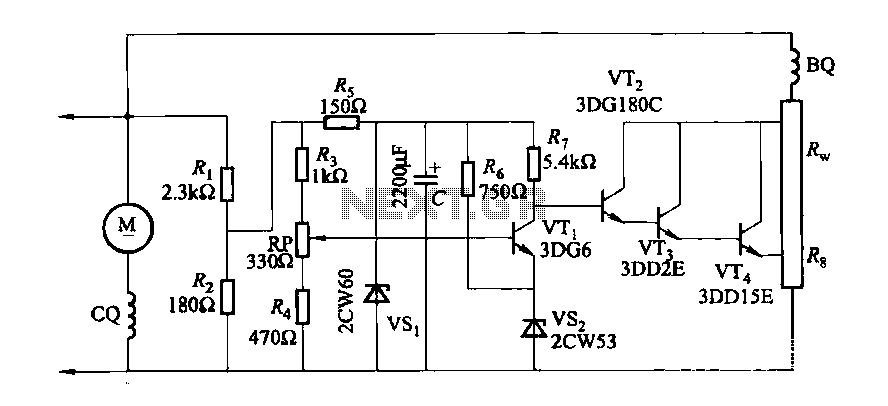
The DC generator automatic voltage regulator circuit is illustrated in Figure 7-53. This circuit is designed for a 40kW, 230V DC shunt complex machine, with a voltage change rate of up to 2.5 percent. In Figure 7-53, BQ represents...
Warning: include(partials/cookie-banner.php): Failed to open stream: Permission denied in /var/www/html/nextgr/view-circuit.php on line 713
Warning: include(): Failed opening 'partials/cookie-banner.php' for inclusion (include_path='.:/usr/share/php') in /var/www/html/nextgr/view-circuit.php on line 713