
SG3524 wiring circuit
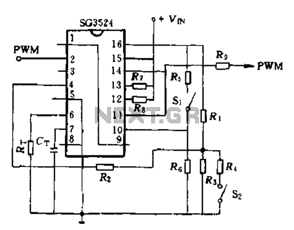
The SG3524 is a versatile integrated circuit designed for pulse width modulation (PWM) applications. In this configuration, it operates primarily as a PWM generator. The error amplifier within the SG3524 is configured as a voltage follower, which ensures that the output voltage closely tracks the input voltage. This arrangement is crucial for maintaining stability and accuracy in the PWM signal generation.
The ACR (Automatic Control Reference) output is connected to the second PWM output pin, which provides the control signal necessary for modulating the output. The voltage VB is derived from the parallel single-ended output, which allows for effective voltage monitoring and control. This setup is particularly useful in applications where precise control of the output voltage is required.
When the PWM signal is inactive or closed, the output signal ceases, resulting in the motor stopping. This feature is beneficial in applications that require immediate cessation of motor operation to prevent damage or ensure safety. The described PWM control method is not only applicable to DC motors but also extends to brushless electric motors, highlighting the versatility of the SG3524.
In the context of switched reluctance motors, the winding current flows in a single direction, making the PWM control IC an ideal choice. The simplicity of the design facilitates easier implementation in various applications, reducing the complexity typically associated with motor control systems. The SG3524's ability to manage PWM signals effectively makes it a valuable component in modern electronic motor control systems.Here, SG3524 only as a pulse width modulator uses. The error amplifier is connected to a follower form. As shown in Figure 10-7. ACR output connector 2 PWM output pin as the control signal. V. VB and take parallel single-ended output. S, closed, shut off the output of the PWM pulse, the motor stops. Obviously, this method is also applicable to the application of DC motors and brushless electric current control motivation. Since switched reluctance motor winding current only in one direction, so switching power supply PWM control IC is more suitable for Taiwan, more simple.
adding = "0"
Related Circuits
This AC motor speed controller can handle most universal type (brushed) AC motors and other loads up to about 250W. It works in much the same way as a light dimmer circuit; by chopping part of the AC waveform...
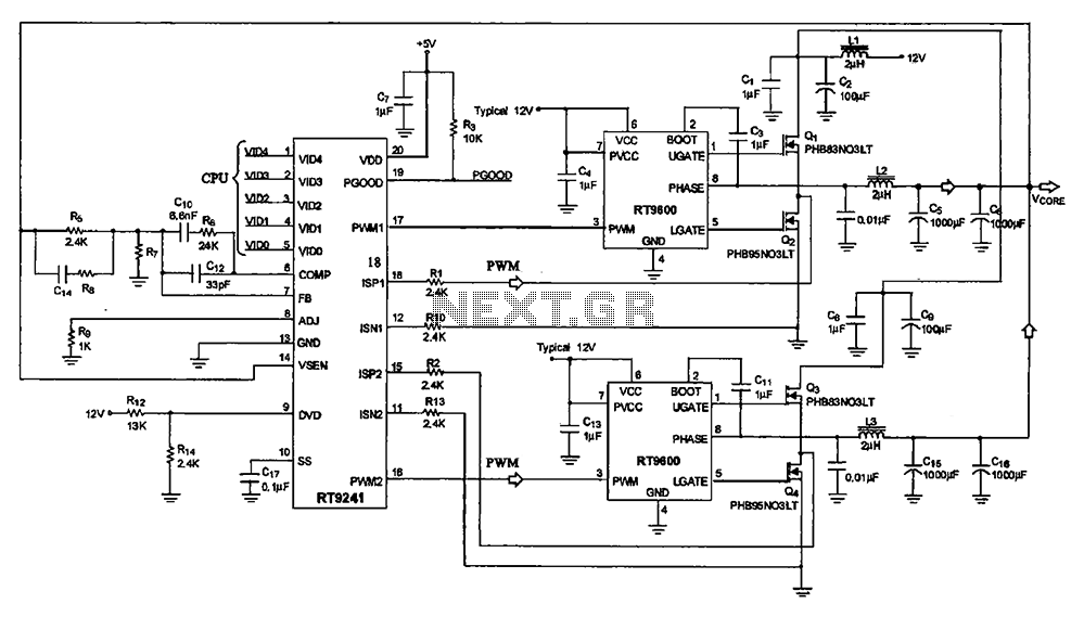
A typical computer motherboard CPU power supply circuit is primarily composed of the main power supply management chip RT9241 and additional components from the power management chip RT9600. The voltage command signal from the CPU is input into the...
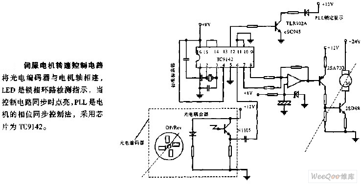
The servo motor speed control circuit connects the photoelectric encoder to the motor shaft. The LED serves as an indicator light for the phase-locked loop (PLL) detection, illuminating when the control circuit is synchronized. The PLL employs a phase...
The LM1036 is a DC-controlled circuit designed for adjusting tone (bass and treble), volume, and balance in stereo applications such as car radios, televisions, and audio systems. It features an additional control input for straightforward loudness compensation. The circuit...
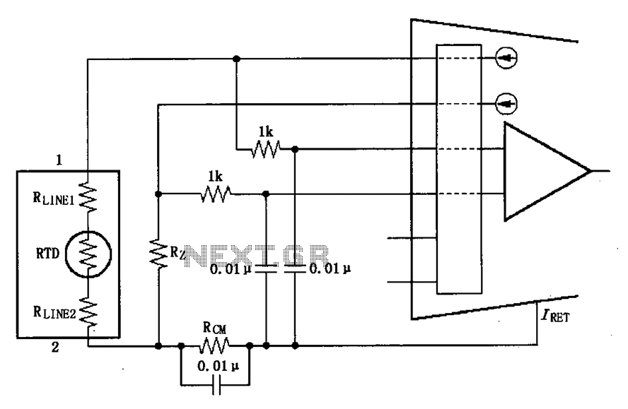
The long wire current loop transmission is susceptible to radio frequency (RF) interference, which can lead to errors in the sensitive input of the XTR108. This interference can occur particularly when the RTD sensor is located at a distance,...

A printed circuit board (PCB) was presented along with a schematic detailing the arrangement of components required for the activation of an LED on the board. The purpose of the PCB is to facilitate planning for the eventual construction...