
555 (TLC555) Relay Driver Circuit
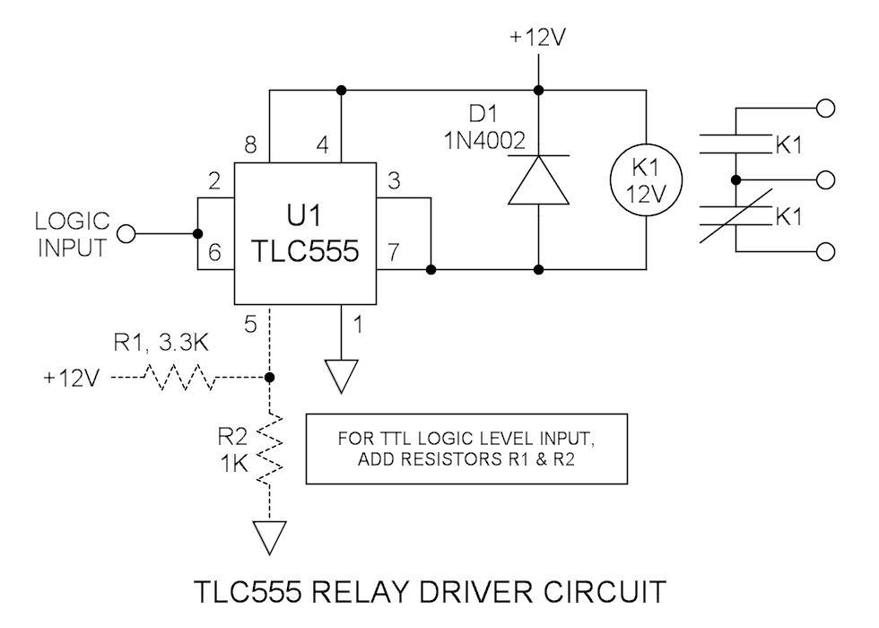
The TLC555 integrated circuit is a versatile timer device that can be configured in various modes, including monostable and astable configurations. In this particular application, the focus is on utilizing the device's output sinking capabilities to control a relay. The TLC555's output pin (pin 3) is designed to handle significant current loads, making it suitable for driving devices such as relays, which require a specific current to activate their coils.
When connecting the output of the TLC555 to a relay, it is crucial to consider the relay's coil resistance and the corresponding current requirements. The selected automotive relay, rated at 40A, is capable of managing larger loads, making it ideal for applications involving motors or high-power devices. The ability to sink 200mA by tying the output and reset pins together enhances the TLC555's effectiveness in this role, ensuring reliable operation without exceeding the current ratings.
The configuration of the trigger (pin 2) and threshold (pin 6) inputs as a Schmitt trigger is a significant feature of this circuit. The wide voltage margin between the upper and lower thresholds (8V and 4V, respectively) provides noise immunity and stable switching characteristics. This is particularly beneficial in environments where voltage fluctuations may occur.
For compatibility with TTL logic levels, the addition of resistors to the circuit allows the TLC555 to interface seamlessly with other digital logic devices. By adjusting the internal voltage divider, the thresholds are lowered to approximately 1.4V and 2.8V, making it suitable for triggering from standard TTL outputs. This adaptability is essential in mixed-logic environments, ensuring that the TLC555 can be integrated into a broader electronic system without compatibility issues.
Overall, the TLC555's features, combined with its capacity to effectively drive a relay, make it a valuable component in various electronic applications, particularly those requiring reliable switching of higher power loads.Many integrated circuits have undocumented features or abilities. This is one of them. The TLC555 output (pin 3) can sink a 100mA load to 1. 28V. The open drain transistor reset (pin 7) can sink 100mA to 1V. Tying both lines together is permissible because they are logically the same polarity and this potentially doubles the sink current ability to 200mA. This is ideal for driving my 133mA relay coil. While it can be seen that the NE555 has the higher current rating, its saturation voltage is grossly inferior and this is a detriment in driving loads without excessive voltage drop. Also it can be seen that the TLC555 is much like TTL in that its sourcing ability is far less than its sinking ability.
However for driving a relay, we are interested only in current sinking properties. This is a 40A automotive relay (contactor) that I selected for this application. Since its coil current exceeds the TLC555 output sink current rating, it is a good candidate. Manufacturer or part number is unknown. What is the difference between a relay and a contactor There is no clear difference other than perhaps current rating and/or application to me, relays are anything from signal devices to approx 20A. Anything rated at 40A or larger, or is used in power applications is a contactor. The trigger input (pin 2) and the threshold input (pin 6) pins are tied together ”this is commonly done.
With a 12V supply, the upper threshold is 8V and the lower is 4V. The two voltage levels, being far apart, make a great Schmitt trigger. This may be driven directly by 4000series CMOS logic that is also powered via 12V. To make it compatible with TTL logic levels, simply add the two resistors that are shown in the schematic. This loads down the internal divider to a lower voltage. The calculated levels are approx. 1. 4 and 2. 8V respectively. 🔗 External reference
Related Circuits
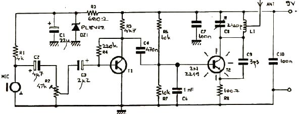
This FM transmitter electronic project operates in the FM band with a transmission power of approximately 250 mW. The circuit is straightforward and utilizes common transistors and electronic components. The T1 transistor, which may be a BC107, BC171, or...
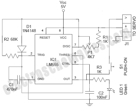
A servo is an error-sensing feedback control mechanism used to correct the performance of a system. A servo motor is a DC motor equipped with a servo mechanism. A servo motor is an electromechanical device that utilizes a closed-loop control...

User Agreement & Disclaimer Disclaimer: All files are found using legitimate search engine techniques. This site does not condone hacking into sites to create the links it lists. It is assumed that all links found on the search...
When the phototransistor is struck by IR light, it conducts, and the voltage between the 1 MΩ resistor (arbitrary) and the phototransistor drops from VCC to lower values. When the voltage drops lower than VCC/3, the 555 is triggered...
Electronics tutorial on mesh current analysis and examples of mesh analysis used to analyze complex electrical circuits in DC theory. Mesh current analysis is a powerful technique used in circuit analysis to determine the currents flowing in the loops of...
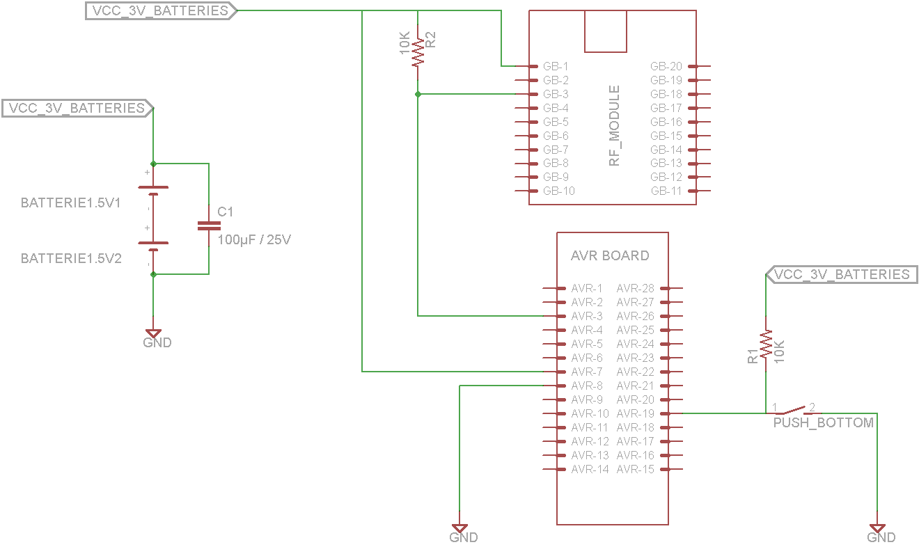
This tutorial demonstrates concepts for creating a lamp with dual actuation. The lamp can be controlled through a parallel switch or by a relay that is managed using an RF module based on the ZigBee protocol (IEEE 802.15.4). The...