
Schematic Diagram 250mW FM transmitter electronic circuit
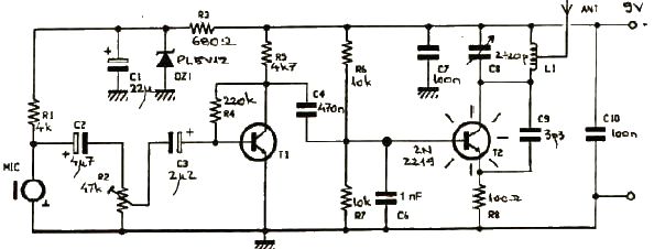
The FM transmitter circuit is designed to provide a compact and efficient solution for low-power audio transmission. The choice of transistors such as BC107 or BC171 ensures that the circuit maintains a reasonable level of performance while being readily available and cost-effective. The audio preamplifier stage, using transistor T1, is critical for capturing sound from the microphone and boosting it to a suitable level for modulation.
The variable resistor R2 plays a significant role in controlling the gain of the audio signal, allowing the user to tailor the audio input to prevent distortion and ensure optimal transmission quality. Care should be taken to avoid overmodulation, which can occur if the audio signal is too strong, leading to interference and loss of clarity in the transmitted audio.
The Hartley oscillator configuration formed by T2 is essential for generating the FM signal. The frequency of the oscillator is determined by the values of C8, C9, and L1. The tuning capability provided by these components allows the user to select a specific frequency within the FM band, accommodating different broadcasting needs. The design of the L1 coil, with its specified number of turns and dimensions, is crucial for achieving the desired inductance and ensuring stable operation of the oscillator.
Overall, this FM transmitter project exemplifies a practical application of basic electronic components to create a functional device for audio transmission. Proper assembly and tuning of the circuit will yield a reliable transmitter suitable for various audio broadcasting applications.This FM transmitter electronic project works in FM band and it has a transmission power around 250mW. This FM transmitter electronic circuit is very simple and is based on some common transistors and electronic parts.
T1 transistor can be a BC107, BC171 or equivalent, and is used as an small audio preamplifier that amplify the audio signal from t he microphone. Adjusting the R2 variable resistor, audio signal level from the input ( microphone ) can be adjusted until will be delivered to the T1 preamplifier (an over amplified signal applied to T1 can produce an overmodulation). From T1, signal is delivered to T2 which form an Hartley oscillator (frequency of this oscillator depends of C8, C9 and L1).
The transmitter frequency oscillator works in FM band 87. 5-108 MHz and can be set, adjusting C8 capacitor and L1 coil. L1 coil must have four turnings on a 0. 8-1 mm cylinder support with a 6 mm diameter (space between each wire must be around 1 mm ). 🔗 External reference
Related Circuits
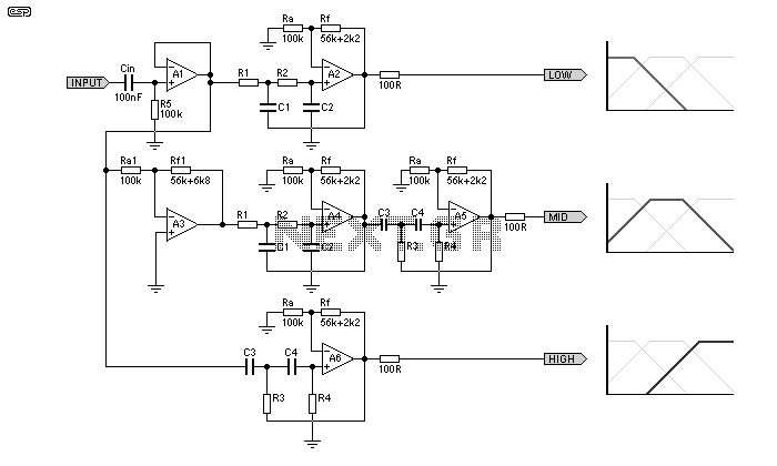
A simple 3-way crossover, intended for triamping Hi-Fi systems. This is a conventional 12dB / Octave unit, and cannot be expected to have the same performance as a Linkwitz-Riley aligned filter network. It will still be a vast improvement...
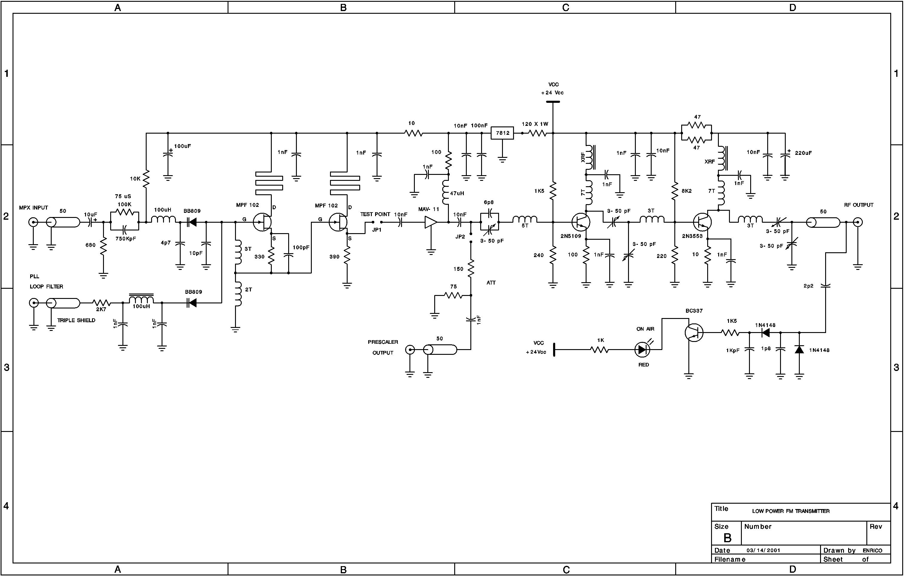
A low power FM pirate radio. The output power is approximately +35 dBm (3.16 watts) over a 50-ohm load and operates on a +24-volt power supply. The project consists of a Hartley oscillator (modulated VCO) and three stages (Class...
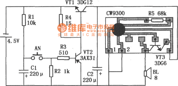
The timing doorbell circuit utilizing the CW9300 is depicted in the provided diagram. This circuit features a timing function that, upon pressing the button, plays music for a specified duration. If the button is pressed again immediately after releasing...
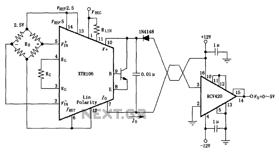
The IN4148 series diode is connected in the V+ line and configured in a loop to prevent damage from reverse voltage conditions. The diode exhibits a forward voltage drop of approximately 0.7V, which affects the supply voltage. The circuit...
For the past few days, research has been conducted on an intriguing boost circuit known as the Joule Thief. The original schematic can be found through online resources. The Joule Thief is a simple yet effective boost converter circuit designed...
An AM radio receiver circuit utilizing an FM IC chip as the primary component. This AM radio receiver circuit incorporates hand-wound coils to adjust the frequency within the AM bandwidth. The AM radio receiver circuit is designed to capture amplitude-modulated...