
Automation of Lamp Relay Controlled with RF
The circuit design incorporates a dual actuation mechanism that enhances user convenience by allowing control through both a manual switch and a wireless RF module. The RF module operates on the ZigBee protocol, which is well-suited for low-power, low-data-rate applications such as remote control of lighting systems. This approach allows for seamless integration into existing home automation systems.
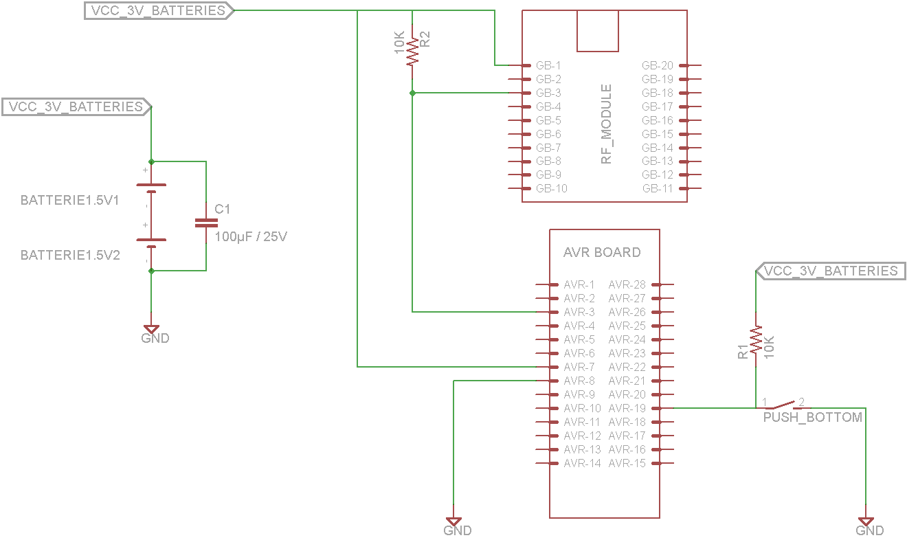
The schematic includes a relay module that acts as a switch to control the power supplied to the lamp. When the parallel switch is activated, it directly completes the circuit to the lamp, allowing for manual control. Simultaneously, the RF module listens for commands sent from a ZigBee-compatible remote or control panel. Upon receiving a signal, the RF module triggers the relay, switching the lamp on or off as per the command.
In terms of component layout, the RF module is connected to a microcontroller that interprets the incoming signals. The relay module is interfaced with the microcontroller, allowing it to control the high-voltage circuit safely. The entire assembly is designed to fit within a standard electrical box, ensuring that it meets safety standards and does not interfere with the aesthetics of the installation.
Power supply considerations must be addressed, ensuring that the RF module and microcontroller receive adequate voltage and current without exceeding their ratings. Additionally, proper isolation techniques should be employed between the low-voltage control circuits and the high-voltage relay to prevent any risk of electric shock.
Overall, this dual actuation lamp design provides flexibility and ease of use, making it a valuable addition to modern smart homes.This tutorial shows concepts for make a lamp withdual actuation. Through aparallelswitchor by relay controlled with RF Module (based on protocol of ZigBee- IEEE 802. 15. 4). The circuit one is a receiver. This circuit controls the load and have a Relay Module, RF Module and parallel switch. It`s responsiblefor receive commands and switch the load. I t goes inside the electrical box in the wall. 🔗 External reference
Related Circuits

A high-quality QRP transmitter, named NEXUS 6, is designed to explore issues related to extremely narrow bandwidth communication. This device is not merely a simplified version of a QRP transmitter; it aims to create a cost-effective system that can...
The following circuit illustrates a BC547 transistor used in an output relay delay audio amplifier circuit diagram. Features include the immediate disconnection of the speaker when the... The BC547 transistor is a widely utilized NPN bipolar junction transistor, often employed...
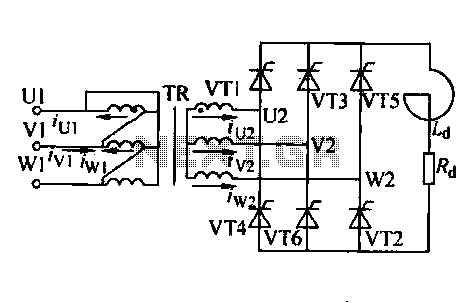
Trigger circuit routing forms include various types such as simple trigger circuits, single-junction transistor trigger circuits, synchronous sine wave trigger circuits, sawtooth transition phase shift (synchronous) trigger circuits, and integrated trigger circuits. This section presents individual cases for introduction...
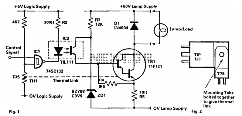
This circuit is designed to drive filament lamps with a nominal rating of 200 mA at 60 V DC using a CMOS logic signal. The lamp or load is connected in series with the Darlington transistor TR1 and an...
It is possible to reduce electricity bills by utilizing alternative power sources. The photovoltaic module, or solar panel, described here, can produce a power output of 5 watts. Under full sunlight conditions, the solar panel generates 16.5V and can...

A voltage-controlled oscillator (VCO) operates similarly to a voltage-to-frequency converter (VFC). Its output frequency is determined by a control voltage input. In the circuit diagram, 'd' represents the amplifier input voltage, which is set to 0.6V, while 'h' denotes...
Warning: include(partials/cookie-banner.php): Failed to open stream: Permission denied in /var/www/html/nextgr/view-circuit.php on line 713
Warning: include(): Failed opening 'partials/cookie-banner.php' for inclusion (include_path='.:/usr/share/php') in /var/www/html/nextgr/view-circuit.php on line 713