
Joule Thief Power Overload circuit

The Joule Thief is a minimalist circuit designed to extract usable voltage from a low-voltage power source, such as a single AA or AAA battery, which may be nearing depletion. The circuit is particularly effective in harvesting energy from batteries that would otherwise be discarded due to insufficient voltage for standard applications.
The core components of a Joule Thief circuit typically include a transistor, a resistor, a toroidal inductor, and a diode. The transistor acts as a switch that alternates the current through the inductor, creating a magnetic field. When the magnetic field collapses, it induces a higher voltage in the inductor, which is then rectified by the diode and can be used to power a load, such as an LED.
The basic operation begins when the circuit is powered on. A small current flows through the resistor into the base of the transistor, turning it on and allowing a larger current to flow from the collector to the emitter. This current energizes the inductor, building a magnetic field around it. Once the magnetic field reaches a certain level, the transistor turns off, causing the magnetic field to collapse rapidly. This collapse induces a high voltage across the inductor, which is then directed through the diode to the load.
The Joule Thief circuit is highly efficient, capable of operating with input voltages as low as 0.5 volts, making it an ideal solution for applications requiring low-power energy harvesting. Its simplicity and effectiveness make it a popular choice among hobbyists and engineers looking to maximize the utility of depleted batteries.Well, this particular circuit is called the Joule Thief, and for those of you that arent familiar with the circuit, here is an image of it. 🔗 External reference
Related Circuits
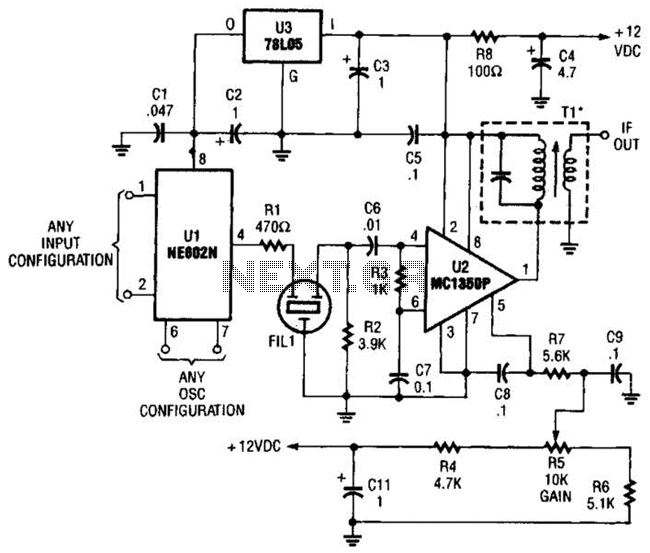
By using an NE602 with a filter and an MC1350P IC, a front end and an IF system for a basic superheterodyne receiver can be built with few parts. Tl is any suitable IF transformer for 262 kHz, 455...
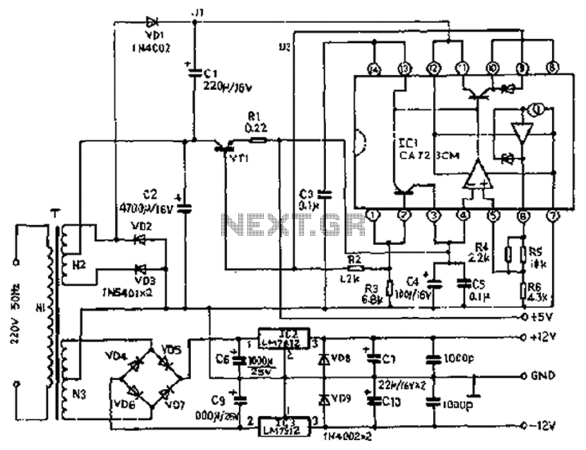
The circuit depicted features a secondary N3 center tap transformer (T) with a common point connecting diodes VD2 and VD3 to positive electrodes, along with capacitors C2, C6, C7, and negative electrodes connected to capacitors C9 and C10. Additional...
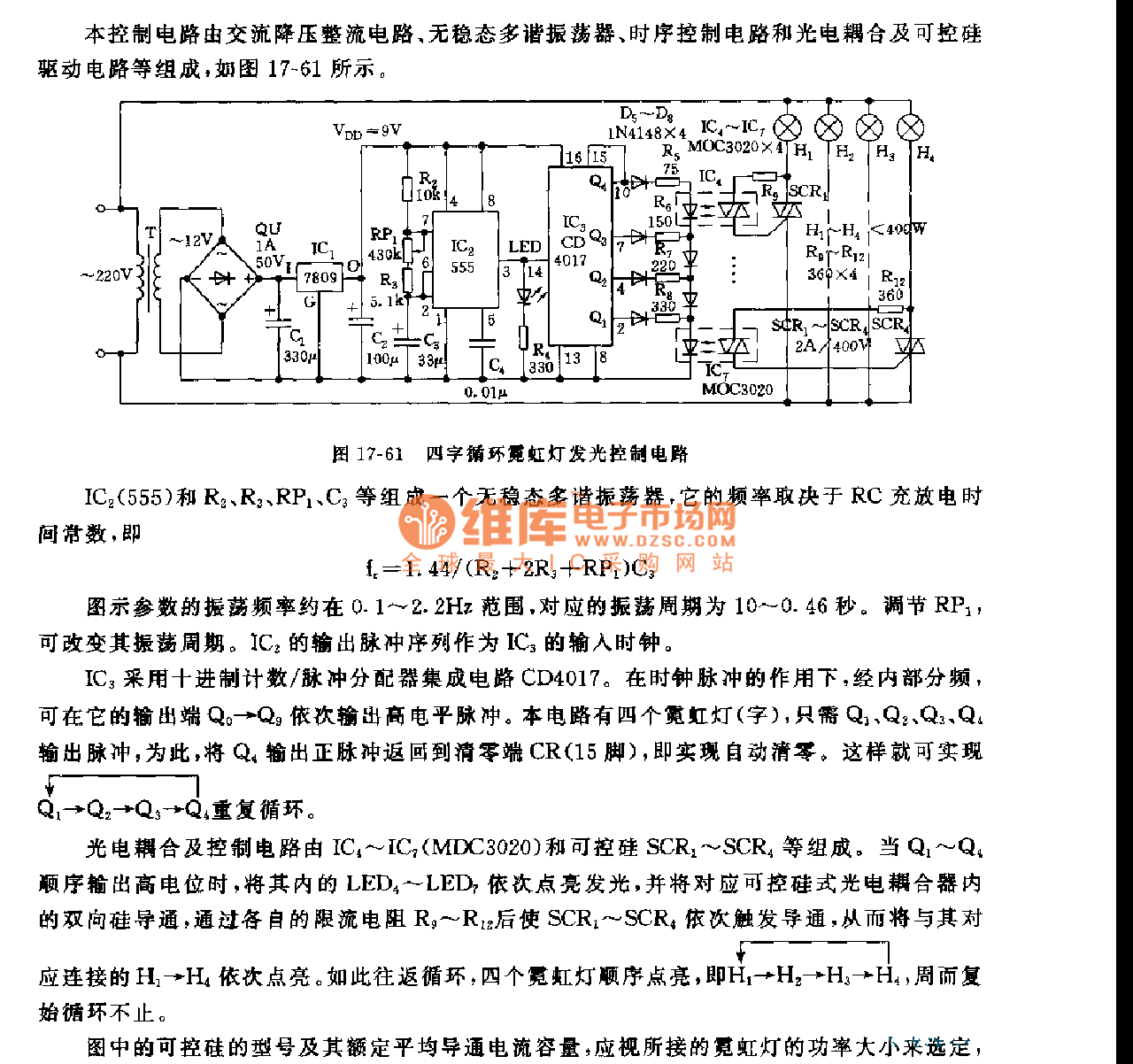
This control circuit consists of an AC step-down rectifier circuit, an astable multivibrator, a timing control circuit, an optocoupler circuit, and an SCR driving circuit, as illustrated in Figure 17-61. The astable multivibrator is formed using IC2 (555), resistors...
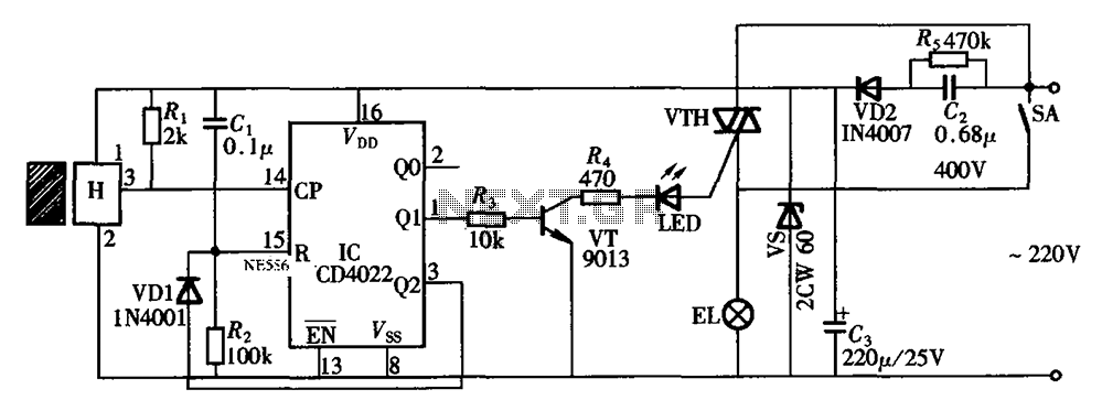
The circuit illustrated in the figure depicts an automatic bathroom light switch system. When the door is opened, the light is activated, illuminating the space. Conversely, when the door is opened again, the light turns off. The circuit comprises...
Many times we needed a stabilized, together regulated power supply and high relatively output voltage. These specifications him it cover our circuit. It’s a circuit that can give in his exit + 40V until + 60V 3A, with simultaneous...
Most universal radio receivers have a very wide bandwidth that is not particularly suitable for radio amateurs. The better models with narrower bandwidth are almost a... Universal radio receivers are designed to operate over a broad frequency range, making them...