
55W (Originally 75W) Power Amplifier
According to the latest information on the Printed Electronics web site, the amp has been downgraded to 55W, which is still more than enough power for all but the most inefficient loudspeakers. The maximum recommended supply voltage is +/-35V, and it is recommended that this is not exceeded (the amp was previously stated to use a +/-42V supply voltage).
The drawings below have been duly amended to reflect this change. It was developed to overcome most of the sonic problems of transistor amplifiers, and incorporates some highly innovative thinking from an experienced designer. It delivers stunning resolution and a pure, sweet sound at very low cost. Both channels are assembled on their own individual 86mm x 75mm boards and mounted on a single 300 x 75 mm ledged heatsink.
It is powered from a 35 volt positive and negative supply, and runs very efficiently in Class AB. Features of this amplifier are its lack of intermodulation and depth of stereo image, unusual for a solid state amplifier. To achieve the best performance, a dual mono power supply is required a schematic is supplied with the boards.
To cap it off, the boards are designed so that it can be built up to 100W per channel (into 4 ohms) with only minor changes to various components and the addition of an extra pair of output transistors on each channel. The circuit diagram for the amp is shown in Figure 1. As can be seen, it is not a complicated amplifier, and all components (excluding power supply) fit onto a single board.
Please Note The schematic shown is conceptual only, at the request of the designer. This has been done to protect the design from possible piracy, due to the extremely good performance from what is (or appears to be) a simple circuit. A full schematic with all component values and assembly instructions is available with the circuit boards.
Normally all ESP projects have complete schematics, but this is not my intellectual property and I will always protect the interests of my contributors. * The pot (P1) is used to set quiescent current. This will normally be adjusted to 100mA. No bias servo is used instead, the diodes D2 and D3 (1N4148 types) are mounted so that they are in contact with the main heatsink.
These must have their leads insulated and be secured using Superglue to ensure good thermal contact. Apply power (preferably with 22 ohm safety resistors installed in series with the +ve and -ve supply lines) with the pot P1 at minimum resistance do NOT connect a speaker at this time. Check for heating of any components, and ensure that the voltage at the output is less than 1 Volt. To adjust the bias current, reinstall the fuses, do not connect a speaker and apply power. Wait for a few minutes for the amp to stabilise, then measure the voltage across one of the 0. 47 ohm output emitter resistors. Carefully adjust P1 when you read a voltage of 47mV, this equates to 100mA. Verify that the output voltage is within about 100mV. After a few minutes (checking for heat in the meantime), check the quiescent current again, and adjust as needed.
WARNING:Mains wiring must be performed by a qualified electrician Do not attempt the power supply unless suitably qualified. Faulty mains wiring may result in death or serious injury. The amp can be operated as a stereo pair form a single supply as shown in Figure 2. Depending on your needs, this will often be quite adequate. Note the capacitor and resistor (R1 and C1) across the mains switch. The capacitor must be rated for at least the full AC supply voltage (i. e. 120V or 240V AC), and all wiring (including the 100 ohm resistor) should be well insulated to prevent accidental contact to the chassis or a finger.
Please read the disclaimer for further suitable warnings about mains wiring. A better solution is to use a dual-mono supply. This shares one transformer, but uses two bridge rectifiers and two sets of filter capacitors. This arrangement minimises any interaction between the amps, and is shown in Figure 3. This supply is virtually identical to the one I presented as Project 04 except for the voltage. Two other differences will be seen if the two are compared My original supply has an inbuilt earth-loop breaker circuit, and this one has an RC snubber circuit across the mains switch. Either of these can be applied on either power supply as required. For both supplies, I suggest a 300VA transformer and 35A bridge rectifiers for best regulation. For 115V countries, the fuse (F1) should be 6A, and in all cases a slow blow fuse is required because of the inrush current of the transformer.
Like the supply in Project 04, the supply voltage can be expected to be higher than that quoted at no load, and less at full load. This is entirely normal, and is due to the regulation of the transformer. For more information on this topic, see Project 4. In some cases, it will not be possible to obtain the rated power if the transformer is not adequately rated.
🔗 External reference
Related Circuits
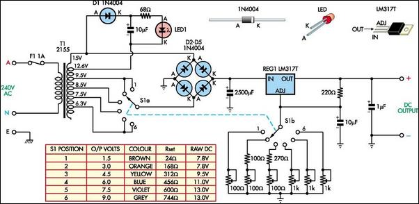
The battery-operated toy has malfunctioned, necessitating repair. Upon disassembly, the battery compartment may be disconnected from the circuitry, or the batteries might be depleted. A solution is to implement a switchable power supply designed to replace one to six...
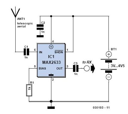
This is a high-performance radio receiver antenna amplifier designed for the entire VHF broadcast and PMR band (100-175 MHz) that can be successfully constructed without... This radio receiver antenna amplifier is engineered to enhance the signal quality and reception capabilities...
Make your own solar powered robot at home using things you probably already have. Transistors, resistor, capacitor, solar battery and flashing LED are available at any electronic store, if you don't already have them. Solar cells out of calculators...
This is an image Schematic. No Description available. The provided input indicates the existence of a schematic image without further descriptive content. In the context of electronic schematics, such images typically represent the arrangement and interconnection of various electronic...

A simple linear voltage-controlled amplifier can be constructed with one operational amplifier (op amp) and two junction field-effect transistors (JFETs). This amplifier can achieve an 80-dB dynamic control range with less than ±0.2% linearity error for 0 V. The described...
Even if simple the circuit, plirej' all condition, regarding the distortion and the response of frequency. The resistance of entry is 250K and the load that can drive is between 100R and 2K. The circuit use negative coupling. His...