
Simple Headphone Amplifier
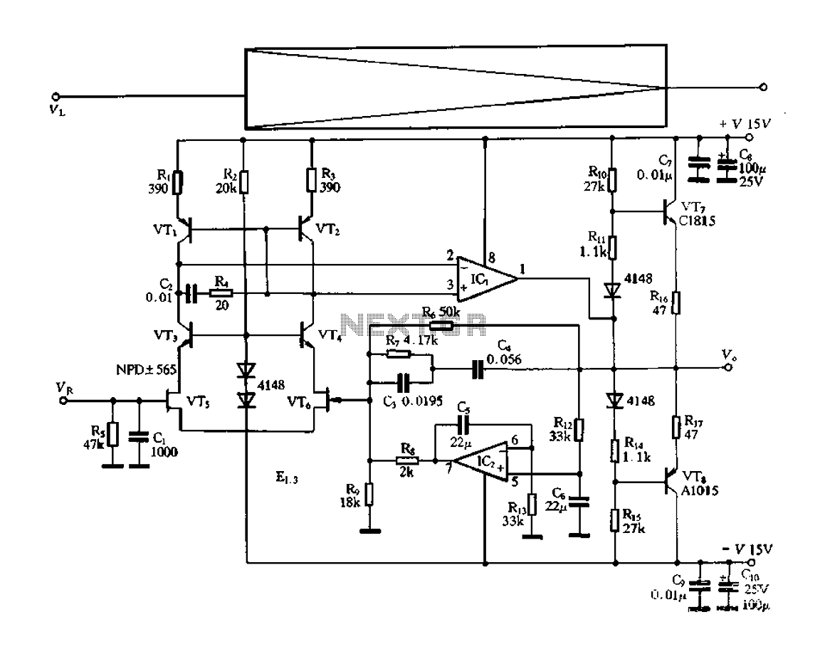
The circuit described is a Class A amplifier featuring a BC308 transistor as the active component. The input resistance is specified at 250 kΩ, which is relatively high, allowing it to interface well with high-impedance sources. The output stage is capable of driving loads in the range of 100 Ω to 2 kΩ, providing versatility for various applications.
Negative feedback is employed in the circuit design to improve linearity and reduce distortion. The use of negative coupling helps in stabilizing the gain and enhancing the frequency response. The circuit operates with a bias current of approximately 14 mA, with a total current draw of around 15 mA, indicating a well-balanced design for efficiency.
The gain of the amplifier is stated to be 25, which suggests that the output voltage can be significantly greater than the input voltage, making it suitable for signal amplification tasks. The power supply requirements range from 6V to 24V DC, providing flexibility in deployment across different systems.
The frequency response of the amplifier with a load of 200 Ω is noted to be from 37 Hz to 470 kHz, with a -1 dB point indicating a relatively flat response across a wide frequency range, suitable for audio applications. The output voltage capability is 1.5V, translating to an output power of approximately 11 mW, which is adequate for driving small speakers or other low-power devices. The total harmonic distortion is measured at 0.5%, indicating a low level of distortion and high fidelity in the amplification process.Even if simple the circuit, plirej' all condition, regarding the distortion and the response of frequency. The resistance of entry is 250K and the load that can drive is between 100R and 2K. The circuit use negative coupling. His exit functions in Class A, having as active charge the BC308 and resistance 39R. The bias current is roughly 14 mA and total 15mA. The gain of unit is 25. The power supply, can be from 6V up to 24V DC. The frequency response with load 200R, it is 37?? - 470K?Z (-1d?), the output voltage is 1.5V (11mW), the distortion 0.5%. 🔗 External reference
Related Circuits
This is a circuit diagram for a simple doorbell. The circuit can be assembled indoors, while the switch should be placed outside, making it easily noticeable for visitors. The operation of this circuit is similar to a previous project. The...
This circuit utilizes the widely available LM3914 integrated circuit (IC), which is straightforward to operate and does not require external voltage regulators due to its built-in voltage regulator. It can be powered from various sources. When the test button...
A 2 x 18W Hi-Fi Stereo Power Amplifier is designed using two TDA2030 integrated circuits (ICs). This amplifier features excellent input sensitivity, low distortion, robust operating stability, and comprehensive protection against overloads and output short-circuits. It is suitable for...
The electronic switch functions as a multifunctional preamplifier. It features a five-way touch electronic switch, a high-speed DC servo RIAA ultralow distortion amplifier, and can control volume, tone, and power amplifier electrical path phase. The TC9152, shown in Figure...

This circuit is sensitive to low-frequency electromagnetic radiation and can detect hidden wiring or the field surrounding a transformer. A radial type inductor is used as a probe, which effectively responds to low-frequency changing magnetic and electric fields. Ordinary...
In addition to its primary function as a headphone amplifier, this circuit can be utilized for various applications requiring a wide bandwidth low-power amplifier. It is designed around an operational amplifier (op-amp), with its output current enhanced by a...
Warning: include(partials/cookie-banner.php): Failed to open stream: Permission denied in /var/www/html/nextgr/view-circuit.php on line 713
Warning: include(): Failed opening 'partials/cookie-banner.php' for inclusion (include_path='.:/usr/share/php') in /var/www/html/nextgr/view-circuit.php on line 713