
Battery Replacement Power Supply
The proposed circuit design features a switchable power supply that can effectively replace battery cells in a variety of applications, especially in toys and portable devices. The core component of this design is the LM317T adjustable voltage regulator, known for its reliability and versatility in providing stable output voltages. The LM317T can output a voltage range that can be adjusted based on the needs of the circuit, making it suitable for powering devices that require different voltage levels.
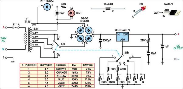
The circuit includes six trimpots, which are variable resistors that allow for fine-tuning of the output voltage. These trimpots are connected to switch S1b, enabling the user to select the desired voltage output by adjusting the respective trimpot. This feature provides flexibility, allowing the user to cater to various devices that may require different operating voltages.
To optimize the performance of the LM317T and reduce heat generation, switch S1a is employed to select different taps from the transformer secondary. This selection is crucial as it helps to minimize the voltage drop across the regulator, thereby reducing power dissipation and improving overall efficiency.
The circuit also incorporates a diode (D1) for protection against reverse polarity, ensuring that the circuit components are safeguarded from potential damage. The inclusion of a 10 µF capacitor serves to stabilize the voltage output, filtering any high-frequency noise that might interfere with the operation of sensitive electronic components.
The LED indicator, powered through the circuit, provides a visual cue of the power status. Its design ensures constant brightness, which is a significant advantage over using an unregulated DC supply, where variations in voltage could lead to inconsistent LED illumination. This feature enhances the usability of the device, providing users with reliable feedback regarding the operational status of the power supply.
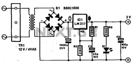
In summary, this switchable power supply circuit is a practical solution for temporarily replacing battery cells in electronic devices, particularly toys. Its design prioritizes efficiency, flexibility, and user feedback, making it an effective tool for both troubleshooting and powering various electronic applications.Your child`s battery toy has failed and you have to fix it. Once you have managed to get it apart, the battery compartment is not likely to be connected to the works or the batteries might have gone flat anyway. The solution is this switchable supply which is designed to replace from one to six dry cells. It is not intended to replace the batterie s on a permanent basis, as in most cases this is not practical. The heart of the supply is an LM317T adjustable 3-terminal regulator and six trimpots selected by switch S1b. The other pole of the switch, S1a, is used to select taps on the transformer secondary, to minimize power dissipation in the LM317T.
The table shows the trimpot settings for the six voltage outputs. Diode D1 and the 10 µF capacitor and the LED provide power indication. This has the advantage of constant brightness which would not be obtained if the LED was run from the unregulated switchable DC. 🔗 External reference
Related Circuits
This is a supply voltage monitor circuit, which serves as an indicator to show if the power supply is in good condition. It is designed using the IC 555 timer. The supply voltage monitor circuit utilizes the versatile 555 timer...
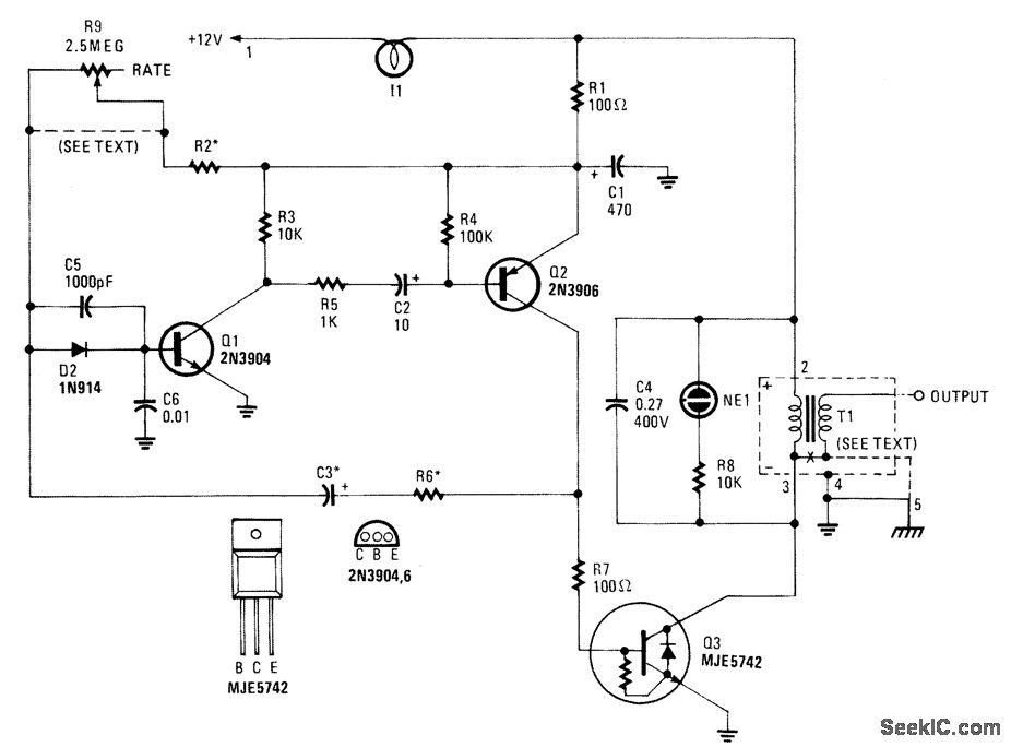
This high-voltage pulse supply generates pulses up to 30 kV. Transistors Q1 and Q2 create a multivibrator in conjunction with peripheral components R1 through R6 and capacitors C1, C2, C3, C5, C6, and diode D2. Resistor R9 adjusts the...
The first prototype PCB has been completed, but concerns arise regarding the heat generated when utilizing the BMS at maximum power in an ultralight hybrid electric vehicle application. At 30A continuous and 50A burst, nearly 20W of loss occurs....
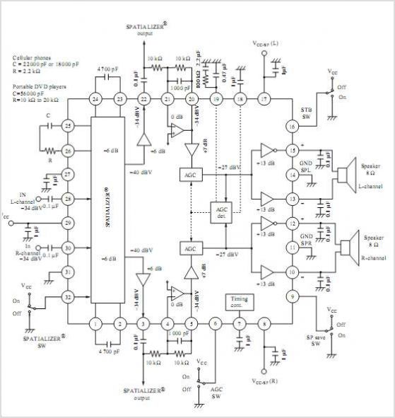
AN12979A is a stereo BTL amplifier that includes an AGC circuit to prevent clipping at the speaker output. This integrated circuit (IC) can perform mode changes via the I2C bus control system, allowing for functions such as toggling the...
Most small portable radios require a 3-V supply, which is typically provided by two AA or AAA batteries. Many of these radios are equipped with a charger socket since rechargeable batteries are an option. When used in a stationary...
The charger in this project is designed to charge two AA NiMH or NiCd cells of any capacity (as long as they are the same) at approximately 470mA. It will charge 700mAh NiCds in about 1.5 hours, 1500mAh NiMHs...
Warning: include(partials/cookie-banner.php): Failed to open stream: Permission denied in /var/www/html/nextgr/view-circuit.php on line 713
Warning: include(): Failed opening 'partials/cookie-banner.php' for inclusion (include_path='.:/usr/share/php') in /var/www/html/nextgr/view-circuit.php on line 713