
+5V 1.6A precision switching power supply circuit
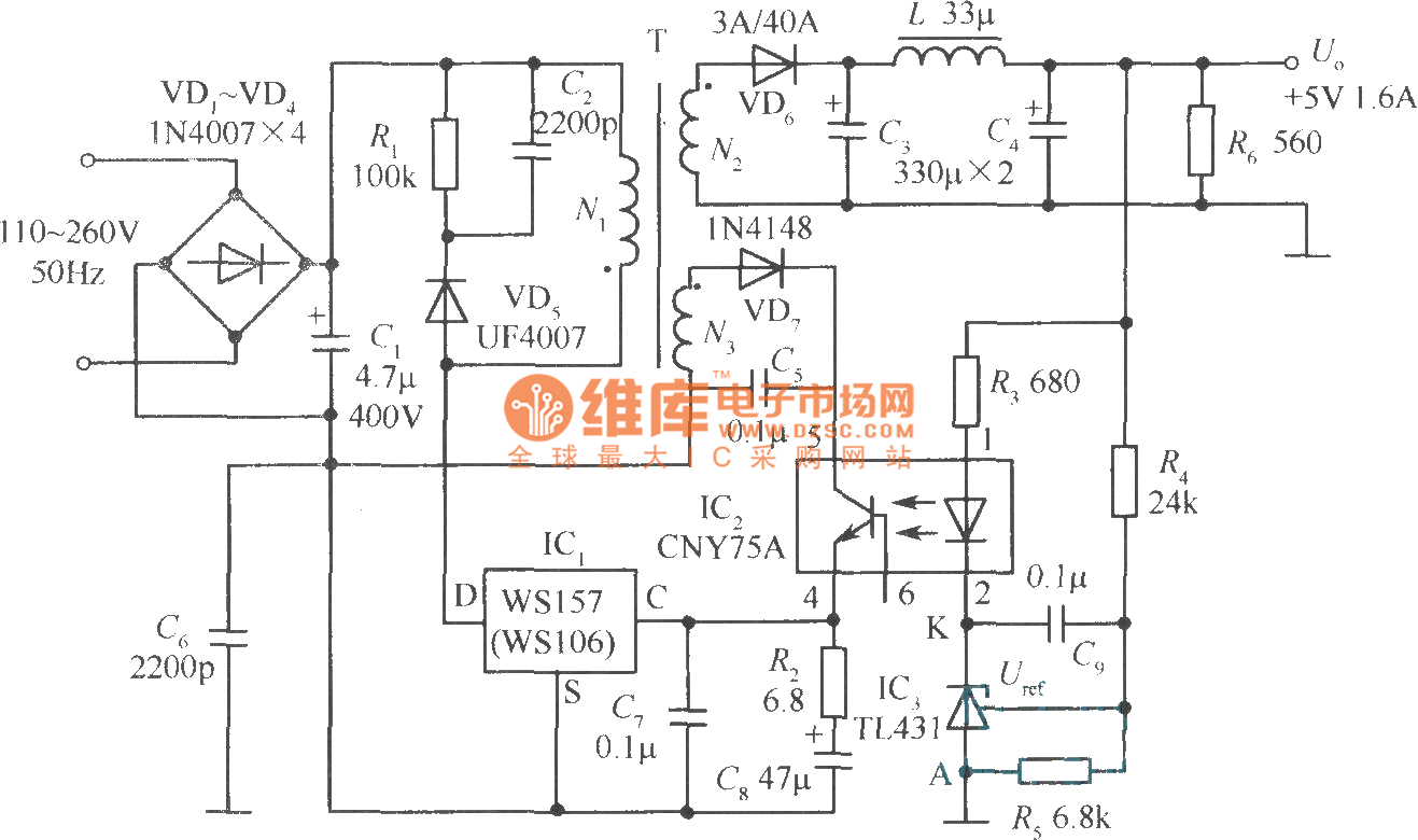
The +5V, 1.6A precision switching power supply circuit is designed to provide a stable voltage output with minimal ripple, making it suitable for sensitive electronic applications. The circuit employs a photoelectric coupler (CNY75A) to isolate the control circuitry from the high-voltage side, enhancing safety and performance. The adjustable precision parallel regulator (TIA31) is used to maintain a constant output voltage, which is critical for ensuring the reliability of the powered devices.
In this circuit, R3 is the current limiting resistor, which protects the components by preventing excessive current flow. R4 and R5 are configured as sampling resistors, enabling the circuit to monitor the output voltage. When the output voltage (Vo) deviates from the desired level, the feedback mechanism compares the voltage across the sampling resistors to a stable reference voltage of 2.5V. This comparison allows for precise adjustments to the output voltage, ensuring it remains at the required +5V level.
The overall design of the circuit emphasizes efficiency and stability, making it suitable for applications that require a reliable power supply. The choice of components, such as the CNY75A for isolation and the TIA31 for regulation, reflects a careful consideration of performance and safety in the design of switching power supplies.The +5V, 1.6A precision switching power supply circuit is as shown in the figure. This circuit increases the photoelectric coupler (CNY75A) and the adjustable precision parallel regulator (TIA31). R3 is the current limiting resistor, R4 and R5 are the sampling resistor. When the Vo changes, the sampling resistor will compare with the 2.5V reference voltage o.. 🔗 External reference
Related Circuits
The circuit comprises a 3-stage resistor-capacitor coupled amplifier. When ring button S2 is pressed, the amplifier circuit formed around transistors T1 and T2 gets converted into an asymmetrical astable multivibrator generating ring signals. These ring signals are amplified by...
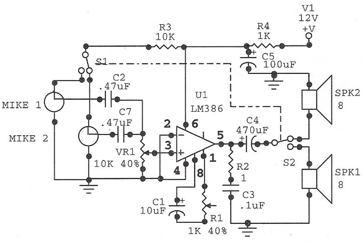
The LM386 is an ideal choice for a door phone application. This device is particularly beneficial in modern urban households, utilizing a condenser microphone and a speaker. The LM386 is a low-voltage audio power amplifier that is commonly used in...

This circuit is designed to check the peak voltage of a signal that can change at any time. Measuring with a multimeter is insufficient for this purpose, hence the recommendation for this circuit. It operates with a positive signal...
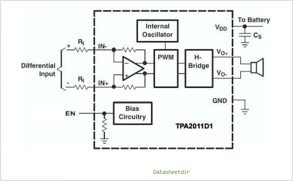
The TPA3007D1 is a 6.5-W mono bridge-tied load (BTL) class-D audio power amplifier featuring high efficiency, which eliminates the need for heat sinks. This amplifier can drive 8-ohm speakers with only a ferrite bead filter required to reduce electromagnetic...
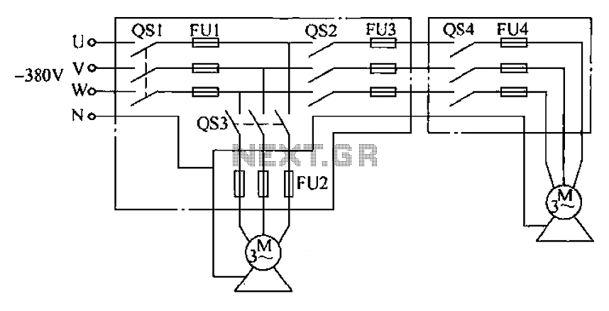
The agriculture and electrical power harrow plow power cord must consist of four rubber cables, with one core wire designated as the ground wire. The traction machine housing must be properly grounded. The two traction power machines are connected...
Here is an interesting circuit for a magnetic proximity switch which can be used in various applications. The magnetic proximity switch circuit, in principle, consists of a reed switch at its heart. When a magnet is brought in the...
Warning: include(partials/cookie-banner.php): Failed to open stream: Permission denied in /var/www/html/nextgr/view-circuit.php on line 713
Warning: include(): Failed opening 'partials/cookie-banner.php' for inclusion (include_path='.:/usr/share/php') in /var/www/html/nextgr/view-circuit.php on line 713