
5V 1A Step Down Switching Regulator using LM2524D and Datasheet
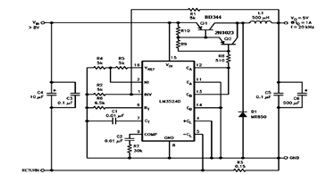
The circuit design features the LM2524D, a highly efficient PWM controller designed for step-down (buck) voltage regulation. This device is capable of converting a higher input voltage into a stable 5V output with a maximum current of 1A. The LM2524D operates by modulating the duty cycle of the output signal, which effectively controls the output voltage.
Key components of the schematic include input capacitors to filter the input voltage and ensure stable operation, an inductor that stores energy during the switching cycle, and output capacitors that smooth the output voltage. The feedback loop, formed by a resistor divider network, monitors the output voltage and adjusts the PWM signal accordingly to maintain the desired output level.
The layout of the PCB is critical for minimizing electromagnetic interference (EMI) and ensuring efficient operation. Proper placement of components, particularly the inductor and capacitors, is essential to reduce parasitic inductance and resistance. The stuffing diagram provides guidance on the assembly of the circuit, indicating the order and orientation of each component.
In summary, this step-down switching regulator circuit utilizing the LM2524D is designed to provide a reliable 5V output at 1A with efficiency and stability, making it suitable for various applications in power management systems. For detailed specifications and performance characteristics, consulting the LM2524D datasheet is recommended.The schematic diagram below circuits 5V/1A Step-Down Switching Regulator using LM2524D Regulating Pulse Width Modulator (PWM). You may see the parameters, PC board layout, stuffing diagram and more in the LM2524D datasheet 🔗 External reference
Related Circuits
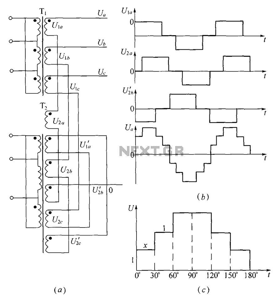
As shown, (a) for the three-phase step wave inverter output transformer winding connections; (b) in the figure, its output waveform. The three-phase step wave inverter is designed to convert direct current (DC) into a three-phase alternating current (AC) output. This...
Integrated AF power amplifiers have experienced significant advancements in recent years, offering enhanced power and ease of use. The TDA1519C from Philips features two power amplifiers that provide 11 W per channel in stereo mode or 22 W in...
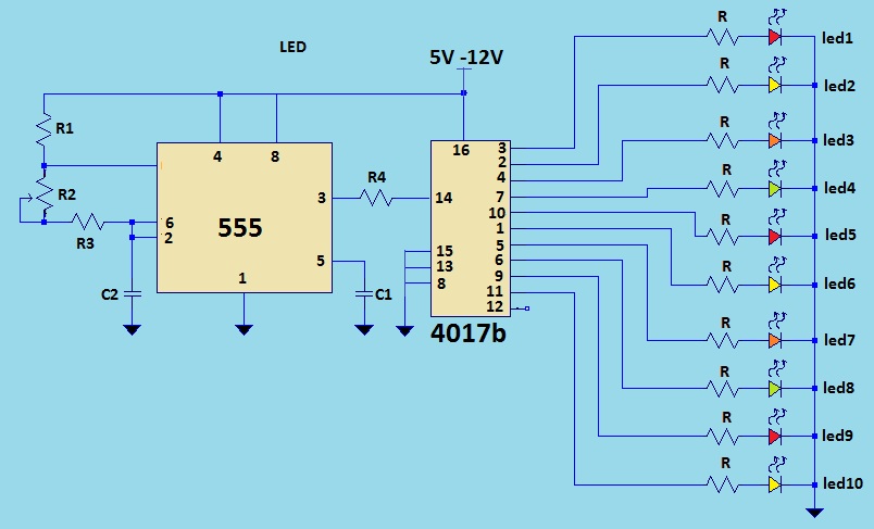
This is a LED sequencer circuit where 10 LEDs light up and turn off sequentially, creating a chasing effect. This simple circuit is suitable for designing lighting decorations on Christmas trees. It can also be used for lighting animations...
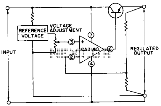
The circuit utilizes a CA3140 BiMOS operational amplifier that is capable of providing a regulated output adjustable from approximately 0 to 24 volts. The circuit is fully regulated. The CA3140 BiMOS operational amplifier is a versatile component that combines the...
In this project, an embedded system is designed for tracking and positioning vehicles using the Global Positioning System (GPS) and Global System for Mobile Communications (GSM). The AT89S52 microcontroller interfaces with various hardware peripherals. The system continuously monitors a...
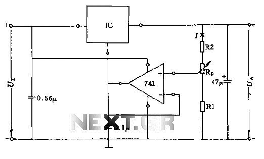
The circuit consists of resistors R1, R2, and RP, where the resistance values play a critical role in determining the magnitude of the current I. This current must exceed the input current of the operational amplifier, which is approximately...