
LED light chaser using 4017
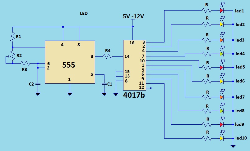
The LED sequencer circuit operates by utilizing a 555 timer configured in astable mode, which generates a continuous square wave output. This output serves as the clock signal for the 4017 decade counter. The 4017 is a popular IC that counts from 0 to 10, activating its output pins sequentially with each clock pulse it receives. In this application, each output pin corresponds to one LED, allowing them to illuminate one after the other, creating a visually appealing chasing effect.
To construct the circuit, the 555 timer is connected to a resistor-capacitor (RC) network that determines the frequency of the output pulses. The frequency can be adjusted by changing the values of the resistors and capacitor in the RC network, allowing for customization of the chasing speed. The output of the 555 timer is connected to the clock input pin of the 4017 counter.
Each of the output pins from the 4017 can be connected to an LED through a current-limiting resistor to prevent excessive current from damaging the LEDs. The LEDs can be arranged in any desired pattern, such as along a strip or in a circular formation, to enhance the decorative effect. By cascading additional 4017 counters and connecting more LEDs, the circuit can be expanded to create longer sequences or more complex lighting patterns.
In summary, this LED sequencer circuit provides a simple yet effective method for creating dynamic lighting effects suitable for various decorative applications, particularly during festive seasons. Its modular design allows for easy modifications and expansions, making it a versatile choice for hobbyists and professionals alike.This is a LED sequencer circuit where 10 led are lighting on and off after one another as if they are chasing each other. This simple circuit is good in designing lighting decoration inChristmastrees. This can be used in lighting animation by just adding more LEDs and drivers. The heart of the circuit is the 4017 decade counter that will give the lighting sequence in the LED. 555 timer serves as the master that gives the clock signal to the decade counter, and this ic controls the rate of the flashes depending on its output pulse frequency. 🔗 External reference
Related Circuits

Trigger circuit routing forms include various types such as simple trigger circuits, single-junction transistor trigger circuits, synchronous sine wave trigger circuits, sawtooth transition phase shift (synchronous) trigger circuits, and integrated trigger circuits. This section presents individual cases for introduction...
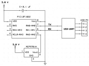
This project outlines a simple and cost-effective method for integrating a digital thermometer and data logging capability into a PC. It utilizes a PIC microcontroller to obtain temperature data from the Microchip MCP9701 sensor and transmits this information to...
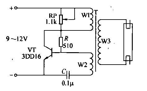
This circuit is designed for the ignition of a direct current (DC) fluorescent lamp rated between 6 to 8 watts. It utilizes a common pole-blocking oscillator that consists of a transistor (VT) and is induced by the secondary side...
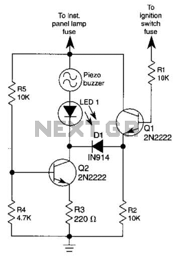
The base of Q1 is connected to the car's ignition circuit; the easiest point to make that connection is at the ignition switch fuse in the car's fuse panel. Also, one side of the piezoelectric buzzer is connected to...
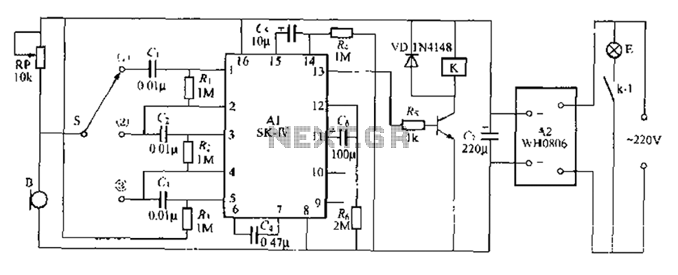
This circuit is a robust light control delay switch with strong anti-interference capabilities. It requires a specific sequence of claps to activate the lamp, which will illuminate for a predetermined duration before automatically turning off. The circuit design is...

The circuit diagram of an AM transmitter circuit based on three transistors. With correct tuning and a matching antenna, the transmitter can effectively transmit amplitude-modulated signals. The AM transmitter circuit utilizes three transistors configured to amplify and modulate the input...