
Adjustable output voltage regulator circuit diagram
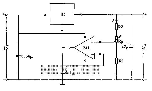
The described circuit utilizes resistors R1, R2, and RP to regulate current flow, ensuring that the operational amplifier operates within its specified parameters. The current I, which is crucial for the amplifier's performance, must exceed 1mA to maintain functionality. The output voltage plays a significant role in this relationship; as the output voltage approaches its maximum, the necessary current I must also increase to match this requirement.
Resistor R1's value is particularly important, as it must be greater than 0.5V to provide stability to the operational amplifier's low output voltage. This stability is vital for the proper functioning of the circuit, especially when dealing with low voltage outputs. The minimum output voltage is influenced by the voltage across UR1 and the voltage from the integrated voltage regulator (UR). This ensures that the circuit maintains a consistent output even under varying load conditions.
The maximum output voltage is determined by the configuration of the circuit, specifically by the relationship between the supply voltage (Us) and the voltage across R2 (UR2). In the provided example, with Us set to 1.5V and UR2 at 1V, the maximum output voltage is calculated to be -2.5V. This indicates the circuit's ability to handle negative voltages, which may be necessary for certain applications.
In summary, this circuit design emphasizes the importance of resistor values and their impact on current and voltage regulation within an operational amplifier setup. Proper selection and configuration of these components are essential for achieving the desired performance and stability of the circuit.Circuit R1 R2 + RP + size branch resistance value determines the magnitude of the current I, the current should be greater than the input current of the operational amplifier, is about I = 1mA. It depends on the output voltage as low as UAmin. Therefore, when the output voltage is adjusted to the maximum value of the current I should be correspondingly larger. Resistor R1 value should be greater than the operating range of the R1 voltage 0.5V, in order to stabilize the op amp's low output voltage.
Minimum output voltage is determined by UR1 + UR, UR integrated voltage regulator constant voltage. The maximum output voltage is determined by UeX (-Us + UR2). If Us = 1.5V, UR2 = 1V, then Umax FUe = -2.5V.
Related Circuits
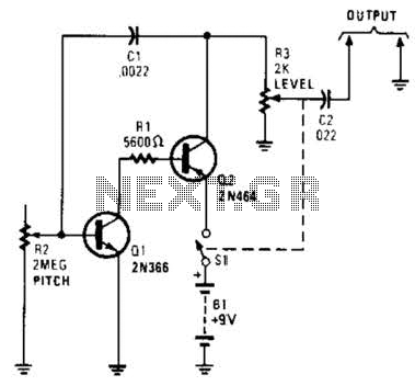
In its simplest form, a voice-over unit is just a microphone and change-over switch feeding an amplifier, the output from the microphone having priority over the amplifiers audio signal when the "push-to-talk" switch is pressed. In this circuit, a...
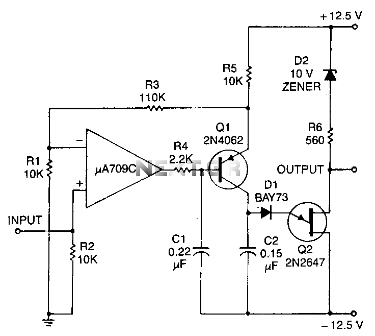
This circuit consists of a UJT oscillator where the timing charge capacitor C2 is linearly dependent on the input signal voltage. The charging current is determined by the voltage across resistor R5, which is precisely controlled by the amplifier....
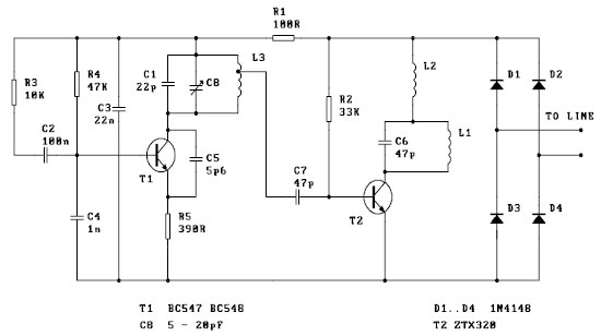
This is a basic telephone broadcaster or transmitter designed for eavesdropping on telephone conversations. The circuit can also function as a wireless telephone amplifier. A key feature of this phone transmitter is that it derives its power directly from...
Useful for troubleshooting audio, video, and lower frequency RF amplifiers. This circuit generates a signal that is rich in harmonics. The circuit designed for troubleshooting audio, video, and lower frequency RF amplifiers is crucial for diagnosing issues in these systems....
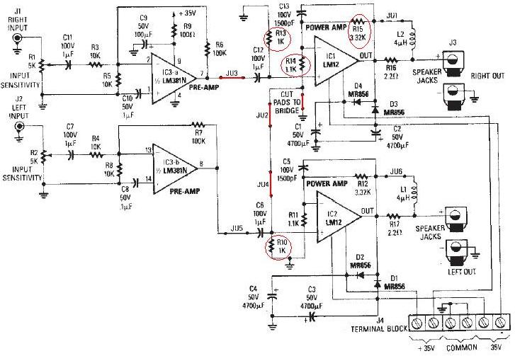
The LM12 audio amplifier circuit is designed to deliver high output power for 8 ohm or 4 ohm load impedances. The maximum output power provided by the LM12 audio amplifier is approximately 60 watts for a 4 ohm load...
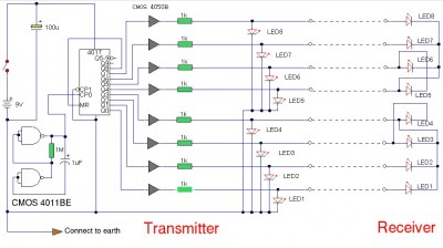
The LAN tester circuit can also test cables such as telephone, coaxial, LAN, and others. This circuit uses LEDs as the main indicator device. The LAN tester circuit is designed to verify the integrity and functionality of various types of...