
5V Dial Tone Circuit Circuit
The circuit design employs a versatile timer-counter that can be substituted with various models, provided they produce square wave outputs in the desired frequency range. This flexibility allows for the incorporation of different timer-counter ICs, facilitating easy accessibility and cost-effectiveness in the design.
The 82C54 timer-counter serves as the primary frequency generator, producing two distinct square wave outputs at frequencies of 350 Hz and 440 Hz. These frequencies correspond to the standard frequency components of a telephone dial tone. The outputs from U1 are then passed through the filtering networks formed by R1/C1 and R3/C2, which smooth out the square waveforms into more sinusoidal shapes, reducing the presence of high-frequency noise and harmonics.
The mixed output from the filtering stage is combined using resistors R2 and R4, which effectively blend the two frequencies to create a composite signal. This mixed signal is then fed into an operational amplifier configured in a Sallen-Key topology, which serves as a bandpass filter centered at 395 Hz. This specific frequency is strategically chosen as it lies midway between the two original frequencies, allowing for optimal tone generation while attenuating any unwanted frequencies outside the intended passband.
The use of a Sallen-Key filter configuration ensures that the output maintains a desirable amplitude and phase response, critical for maintaining the integrity of the dial tone. The operational amplifier amplifies the filtered signal to the required level for telephone line compatibility.
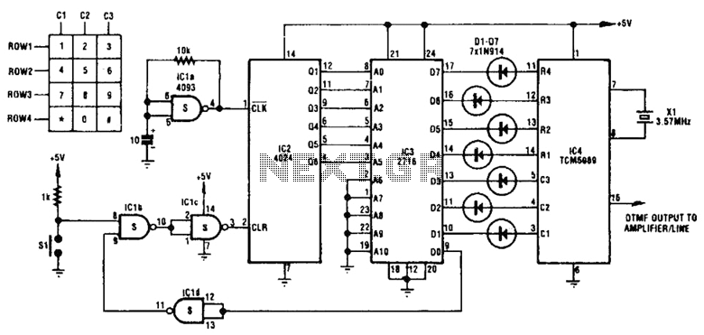
In summary, this circuit efficiently generates a precise dial tone using basic electronic components, ensuring that it can be easily replicated and modified for various applications within telecommunications. The design's reliance on standard components enhances its accessibility for hobbyists and professionals alike, making it a practical solution for generating telephone tones. This circuit uses inexpensive, common components to generate a precise dial tone for phone applications (see the figure). Ul (an Intel 82C54 timer-counter) generates 350 and 440Hz square waves that are filtered by Rl/Cl and R,JC2, and mixed together by resistors R2 and R4.
An operational amplifier configured as a 395-Hz, Sallen-Key, second-order bandpass filter (halfway between 350 and 440 Hz) removes unwanted signal harmonics. Almost any timer-counter can be used as the signal source, so long as it produces roughly square-wave outputs. 🔗 External reference
Related Circuits
The integrated circuit LA3607 enables the configuration of a 7-band graphic equalizer for a single audio channel by incorporating additional capacitors and variable resistors. The cutoff frequency can be modified using variable resistors. It demonstrates high stability when handling...
The welder no-load power saver circuit consists of a current detection control circuit and a power saving control circuit, as illustrated in the accompanying chart. The current detection control circuit includes a current transformer (TA), a bridge rectifier (UR),...
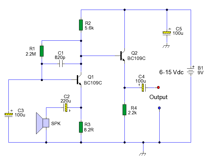
This circuit enables the use of an inexpensive loudspeaker as a microphone. Sound waves that reach the speaker cone create fluctuations in the voice coil. The movement of the voice coil within the speaker's magnetic field generates a small...
Many households still use tube-type television sets. Connecting these large televisions to a stereo system to enhance sound quality is usually straightforward, as numerous SCART to Cinch adapters are available in accessory shops. However, some television sets may present...
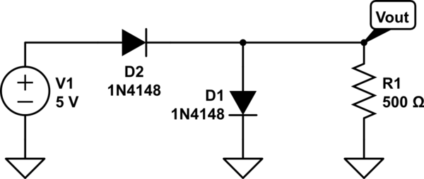
The two diodes will fail. It is advisable to include series resistors for them. If the simulation is successful, the current through the diodes will be excessive. Both diodes do not necessarily need to fail; one may become a...
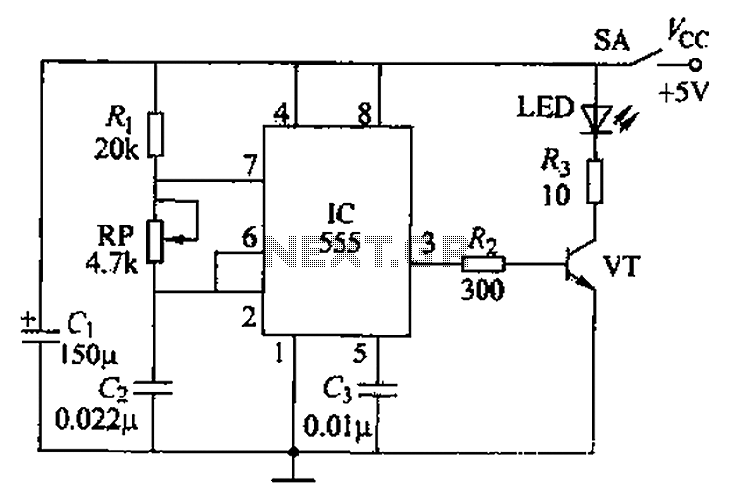
The circuit utilizes a 555 timer integrated circuit along with a transistor (VT) and several external components to create a multivibrator circuit. The charge and discharge time constants, Ti and T2, are defined, where Ti is approximately 0.7 times...
Warning: include(partials/cookie-banner.php): Failed to open stream: Permission denied in /var/www/html/nextgr/view-circuit.php on line 713
Warning: include(): Failed opening 'partials/cookie-banner.php' for inclusion (include_path='.:/usr/share/php') in /var/www/html/nextgr/view-circuit.php on line 713