
5V power supply with overvoltage protection
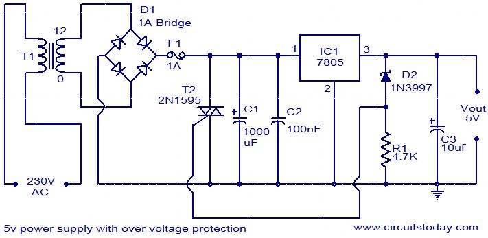
The described circuit is an effective overvoltage protection mechanism specifically designed for TTL IC applications. It addresses the critical issue of supply voltage fluctuations that can lead to component failure. The crowbar circuit utilizes a triac (T1) and a zener diode (D2) to provide rapid response to voltage spikes.
In this configuration, the zener diode is set to a breakdown voltage of 5.6 volts. Under normal operating conditions, the output voltage remains below this threshold, and the zener diode remains non-conductive. However, when the output voltage exceeds 5.6 volts, the zener diode enters its conductive state, triggering the gate of the triac T1. This rapid switching action effectively creates a short circuit across the power supply, leading to an immediate drop in output voltage to zero.
The fuse in the circuit serves as a secondary safety measure. While it may take longer to physically blow, the immediate action of the triac ensures that the sensitive TTL ICs are insulated from prolonged exposure to excessive voltage. The fuse will eventually burn out, providing a fail-safe mechanism that maintains the integrity of the circuit components.
The design of this circuit is crucial in environments where voltage spikes are common, ensuring that TTL ICs and similar devices are protected from damage. The combination of the triac and zener diode allows for a swift response to overvoltage conditions, significantly enhancing the reliability and longevity of the electronic system. This crowbar protection scheme is particularly valuable in industrial applications, consumer electronics, and any system where voltage stability is paramount for operational safety and performance.For circuits using TTL ICs the supply voltage is a great concern and a slight increase in supply from the rated 5V may damage the IC. Using fuses alone does not solve the problem because a fuse may take several milliseconds to blow off and that`s enough time for the IC to get damaged.
In this circuit a crowbar scheme is used in which a triac short circuits the power supply and burns the fuse. The burning time of the fuse is not a concern because the power supply is already shorted by the triac and the output voltage will be zero. When the output voltage exceeds 5. 6 volts the zener diode D2 conducts and switches ON the triac T1. Now T1 acts as a closed switch, shorting the circuit. The output voltage drops to zero and fuse gets burned off. Since the switching of triac takes place within few micro seconds there will be no damage to the TTL ICs or any other such voltage sensitive components in the load circuit.
🔗 External reference
Related Circuits
The schematic of the power supply is illustrated below. It operates using standard household power of 120VAC at a frequency of 50/60Hz, with an adjustable output that can reach up to 25kV or higher. The power supply circuit is designed...
This circuit generates three source-regulated voltages using a minimal number of electronic components. The output DC voltages are +12V, +5V, and -5V. Diodes D2 and D3 perform full-wave rectification while charging capacitor C2 during each half of the alternating...
This document outlines the details of several circuits designed and built for a robot. The first circuit is a voltage regulator intended to supply power to a Raspberry Pi from a 7.2V battery. While the circuit is relatively simple,...

The LT3495, LT3495B, LT3495-1, and LT3495B-1 are low-noise boost converters equipped with an integrated power switch, feedback resistor, and output disconnect circuitry. These devices manage power delivery by adjusting both the peak inductor current and the switch off-time, resulting...
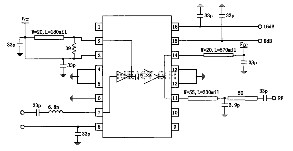
The circuit diagram illustrates the application of a 915MHz RF2155 power amplifier. The radio frequency (RF) signal enters through pin 7, where it is processed by a preamplifier. The output from the preamplifier is further amplified by the power...

The circuit described below is notable for its low power consumption. With a 9V input and no load at the output, it draws only 50 mA, which is significantly lower than the quiescent current of a 78L05 regulator. The...