
Battery powered Pi and servo switch
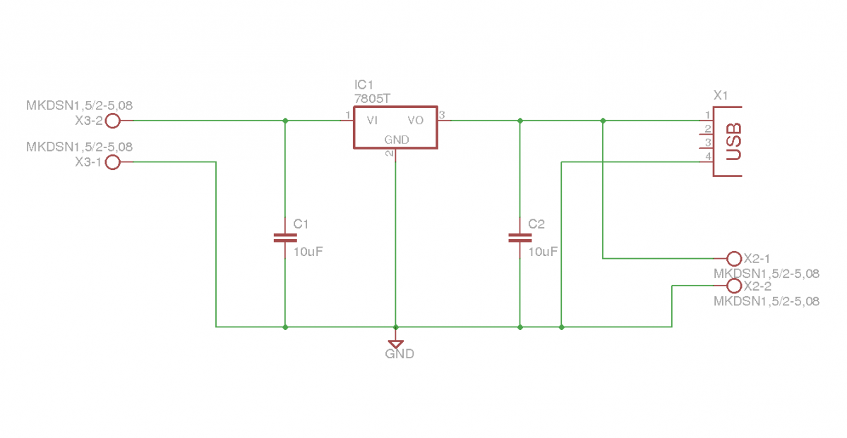
The voltage regulator circuit for the Raspberry Pi is designed to convert the 7.2V from the battery to a stable 5V output, which is the required operating voltage for the Raspberry Pi. The circuit typically utilizes a linear voltage regulator, such as the LM7805, which is capable of providing a maximum output current of 1A.
The circuit configuration includes input and output capacitors to ensure stability and reduce voltage spikes. A capacitor with a value of 0.33 µF is placed at the input of the regulator to filter any high-frequency noise from the battery supply, while a 0.1 µF capacitor is placed at the output to maintain stability under varying load conditions.
Additionally, to enhance the circuit's performance, a heat sink may be attached to the voltage regulator to dissipate excess heat generated during operation, especially when the input voltage is significantly higher than the output voltage. This is crucial to prevent thermal shutdown, which can occur if the regulator overheats.
To facilitate easy connection to the Raspberry Pi, the output of the regulator can be connected to the 5V and GND pins of the Raspberry Pi GPIO header. The circuit can also be equipped with an LED indicator to show when the regulator is powered and functioning correctly.
Overall, this voltage regulator circuit is a practical solution for powering a Raspberry Pi from a higher voltage battery source, ensuring stable operation while integrating user-friendly features.This post will outline the details of a couple of circuits I designed and built for my robot. The first is a regulator to supply my Raspberry Pi with power from a 7.2V battery. Although a simple circuit, it has some features that make it very easy to use to power the pi. 🔗 External reference
Related Circuits
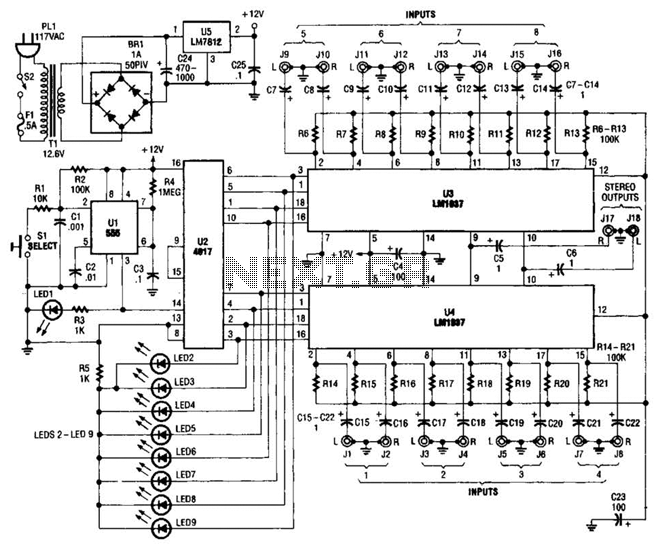
This source is selected by pressing a momentary-contact pushbutton switch (SI). Switch SI is connected to the trigger of a 555 oscillator/timer (U1) configured as a monostable multivibrator, which generates one short output pulse for each press of SI....
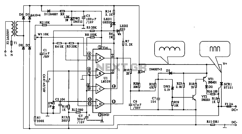
The Chizuru 100Hz channel frequency pulse charging circuit for electric bike batteries is designed to manage the charging process efficiently. It features a step-down transformer (Tl) and a bridge rectifier formed by diodes D5 to D8. The output ripple...
FM Radio has a long history, starting from its development in 1933. Today, FM Radio is an integral part of almost all mobile phones. In a typical mobile phone, the earphone cable acts as the antenna for FM reception,...
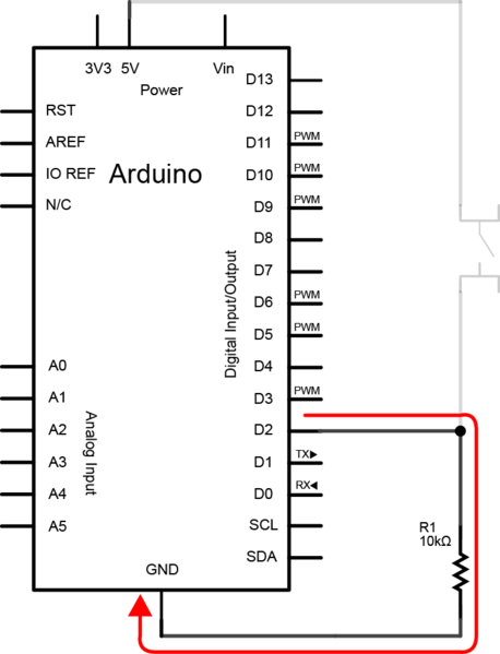
To create the circuit, connect a switch as an input and an LED as an output to the Arduino. The components required include a switch, an LED, a 10kΩ resistor, a 470Ω resistor, a blue or yellow jumper wire,...
This is a straightforward circuit designed for charging lead-acid batteries using the PB137 regulator. The PB137 is utilized in the lead-acid battery charger circuit due to its ability to provide... The PB137 voltage regulator is a linear regulator specifically suited...
This circuit utilizes the widely available LM3914 integrated circuit (IC). The LM3914 is straightforward to operate, does not require external voltage regulators due to its built-in voltage regulation, and can be powered by a variety of sources. The LM3914 is...