
5v regulated solar cell power supply circuit diagram
Component Parts List:
- R1 = 22 ohm, 1W
- R2 = 270 ohm
- R3 = 220 ohm
- R4 = 715 ohm, 1%
- R5 = 3.57K, 1%
- R6 = 1.40K, 1%
- R7 = 1.47K, 1%
- C1 = 0.1 F, ceramic
- C2 = 0.1 F, ceramic
This battery charger circuit is regulated and adjustable, making it suitable for charging most NiCAD batteries. It can accommodate single or multiple battery cells connected in series or parallel, with a maximum battery voltage of 18V. Power transistors Q1 and Q2 are configured as series regulators.
A load cell amplifier can be constructed to reduce costs, as commercial options are often priced between $100 and $300. The proposed load cell amplifier utilizes the AMP04 or INA125 components.
The solar-powered battery charging circuit operates efficiently in bright sunlight, providing a reliable power source for charging batteries. The use of diodes ensures that the current flows in the correct direction, preventing backflow that could damage the solar panel or the batteries. The inclusion of capacitors helps smooth out the rectified voltage, providing stable output levels.
The circuit's design allows for easy adjustment and regulation, making it versatile for different applications, particularly for charging various battery types. The specified resistors and capacitors are selected to optimize performance while maintaining cost-effectiveness.
Overall, this schematic presents a practical solution for harnessing solar energy to charge batteries, demonstrating the integration of renewable energy sources in electronic applications.Powered with solar panel, the circuit will give you 5V pure regulated DC voltage. The circuit is made up of an oscillator transistor as well as a regulator transistor. The solar panel charges the battery when sunlight is bright enough to generate a voltage above 1. 9v. A diode is necessary between the panel and also. This is the schematic diagram of solar powered mobile phone battery charger. The circuit is designed to charge the battery from a source with a lower voltage. Do not use it to charge the battery with the same or lower voltage than the voltage which is generated by the solar panel. For proper operation of. This circuit generates 3 source regulated voltages applying a minimum of electronic parts. The output DC voltage are +12V ; +5V and -5V. Diodes D2 and D3 conduct full-wave rectification, at the same time charging capacitor C2 on each halves of the alternating current cycle.
At the same time, diode D1 with capacitor C1, and. The following diagram is the battery charger schematic for 6V Gel Cell battery type. Component Parts List: R1 = 22 ohm, 1W R2 = 270 ohm R3 = 220 ohm *R4 = 715 ohm, 1% *R5 = 3. 57K, 1% *R6 = 1. 40K, 1% *R7 = 1. 47K, 1% C1 = 0. 1 F, ceramic C2 = 0. 1 F, ceramic. This battery charger circuit is regulated and adjustable to make this circuit able to charge the mosto NiCAD battery. This circuit will work for single cell or multi battery cell which connected with series/parallel connection.
The maximum voltage of the batteries should be 18V maximum. Power transistors Q1 and Q2 are connected as series regulators. I`ve found some interesting schematic of Load Cell amplifier. As we know, load cell amplifier is pretty expensive with fair price range of 100-300 USD. You may built your own load cell amplifier to get the lower cost. Load Cell Amplifier using AMP04: source: Load Cell Amplifier using INA125: source: source: 🔗 External reference
Related Circuits
When the ON/OFF button is pressed once, the equipment goes on and stays on. It goes off when the button is pressed again. The circuit is straightforward. It uses a JK CMOS Flip-Flop with its JK terminals tied high...
Circuit designed to alleviate concerns related to high frequency utilizes a ready-made module, specifically an Aurel audio FM transmitter. This compact circuit board, measuring 2 cm by 4 cm, supports a modulation frequency track and delivers an RF power...
An RF field indicator is needed to verify power stages and transmitter antennas. This radio field indicator allows for the measurement of radiated energy from antennas. An RF field indicator is a crucial device in the field of telecommunications and...
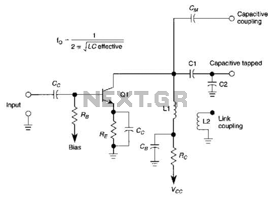
This basic tuned LC amplifier can be used with three output coupling methods: capacitive coupling output, capacitive tapped output, or link-coupled output. The tuned LC amplifier is a fundamental circuit used in various applications, including radio frequency (RF) amplification and...
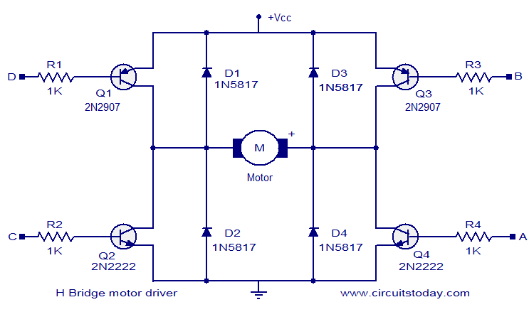
The circuit presented is a simple H-bridge motor driver circuit utilizing commonly available components. An H-bridge is an efficient method for driving motors and is widely used in various electronic projects, particularly in robotics. The circuit illustrated is a...
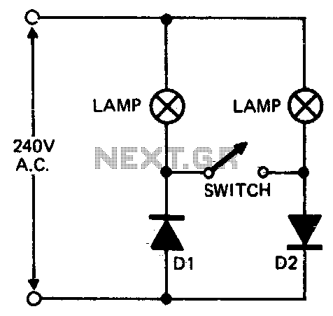
When setting up photographic floodlamps, it is sometimes desirable to operate the lamps at lower power levels until actually ready to take the photograph. The circuit allows the lamps to operate on half-cycle power when the switch is open...