
Soft ON/OFF switch circuit
The described circuit utilizes a JK flip-flop configured as a toggle flip-flop, which is integral for the ON/OFF functionality of the equipment. The JK flip-flop is a bistable multivibrator capable of holding two stable states, which correspond to the ON and OFF states of the device. In this configuration, both the J and K inputs are connected to a high logic level (logic '1'), allowing the flip-flop to toggle its output state with each clock pulse.
The clock signal is generated by the push button switch that serves as the ON/OFF control. When the button is pressed, it momentarily connects the clock input of the flip-flop to a high state, causing the flip-flop to change its output state. This toggling mechanism allows the equipment to remain in its last state until the button is pressed again, creating a user-friendly interface.
To ensure reliable operation, the circuit includes a resistor-capacitor (RC) debounce network connected to the push button switch. This configuration prevents false triggering of the flip-flop due to mechanical bouncing of the switch contacts when pressed. The capacitor charges and discharges through the resistor, smoothing out the transitions and providing a clean clock signal to the flip-flop.
Additionally, the circuit incorporates a RESET button, which allows the user to force the flip-flop into a known state (OFF) regardless of its previous state. This feature is particularly useful for initializing the device or for troubleshooting purposes.
The output of the JK flip-flop can be connected to a relay, which controls the power to the equipment. The relay's state will correspond to the flip-flop's output, thus enabling or disabling the power supply to the device. The design ensures that the relay can be in either state (ON or OFF) when the circuit is powered on, providing flexibility in operation.
This circuit design exemplifies modern electronic control systems that utilize silent push-to-on-push-to-off switches, enhancing user experience while maintaining functionality similar to traditional mechanical switches.When the "ON/OFF" button is pressed once, the equipment goes on and stays on. It goes off when the button is pressed again. The circuit is straight forward. It uses a JK CMOS FlipFlop to with its JK terminals tied high to achieve the toggling action. The clock is provided by the push button used for on/off action. The resistor and the capacitor near the on/off switch debounces the contacts. Note that when the circuit is switched on, the relay may land in a on or off state. It can be brought to the off state by pressing the RESET button. Modern electronic equipment incorporate "push-to-on-push-to-off" switches that do not make the clicking noise as with old equipment. An example of this is the power button on a ATX computer cabinet. Here is a circuit that does the same. It can b 🔗 External reference
Related Circuits
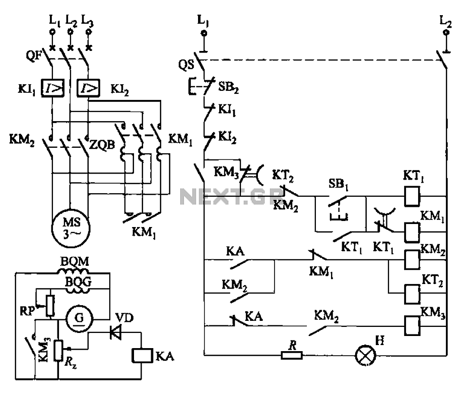
The circuit depicted in Figure 3-187 illustrates the operation of an auto step-down transformer (ZQB). Upon activation, the ZQB transformer initiates a sequence that allows the motor to gradually increase its speed. After a predetermined delay, the ZQB ceases...
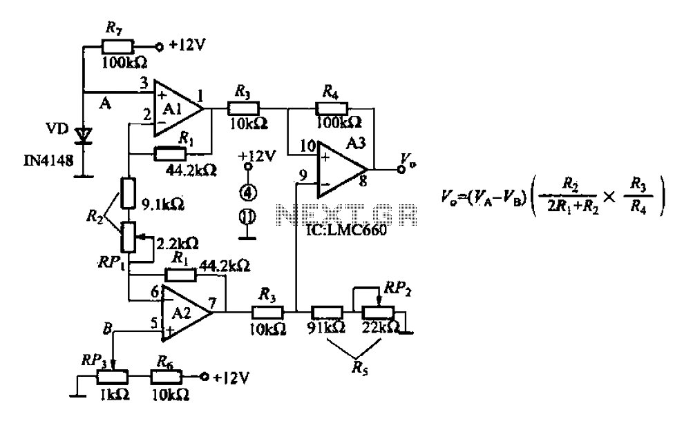
A diode IN4148 temperature circuit is presented. The circuit operates within a temperature range of -25 to 125 degrees Celsius, with an accuracy of 0.5. The core components of the operational amplifier circuit consist of four LMC660 amplifiers. It...

This is a simple design for a voltage regulator circuit using a pass transistor. The design is built around the LM317T. The output current of the LM317T can be increased by incorporating an additional power transistor to share a...
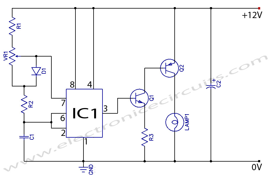
When the potentiometer is in the upper position, the capacitor charges rapidly through both 1k resistors and the diode, resulting in a brief positive interval and an extended negative interval, which dims the lamp to near darkness. Conversely, when...
The buba oscillator initially failed to oscillate. The first step is to check the fundamental components, as minor errors in the values of capacitors, resistors, and inductors can significantly impact performance. It is advisable to measure component values with...
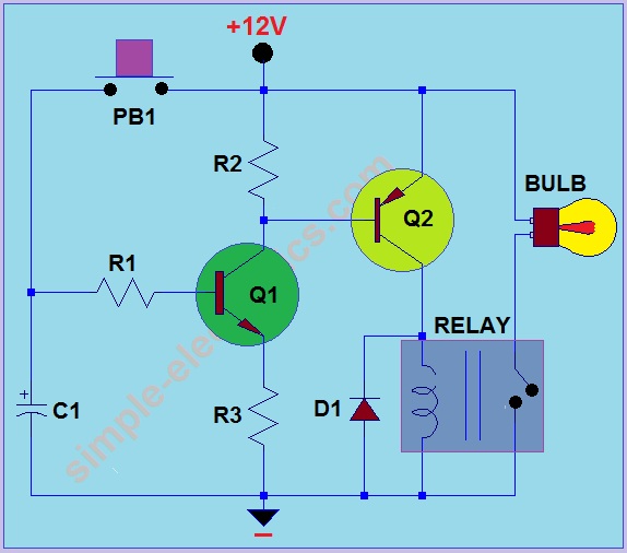
This circuit operates by activating a headlight when the push-button PB1 is pressed. The headlight remains illuminated for a predetermined duration, which can range from several seconds to minutes, before automatically turning off. When PB1 is engaged, capacitor C1...
Warning: include(partials/cookie-banner.php): Failed to open stream: Permission denied in /var/www/html/nextgr/view-circuit.php on line 713
Warning: include(): Failed opening 'partials/cookie-banner.php' for inclusion (include_path='.:/usr/share/php') in /var/www/html/nextgr/view-circuit.php on line 713