
H bridge motor driver circuit

The H-bridge motor driver circuit is a fundamental component in motor control applications. It consists of four switching devices, typically bipolar junction transistors (BJTs) or MOSFETs, arranged in a bridge configuration. This arrangement allows for the control of motor direction by selectively activating pairs of transistors. The diodes D1 to D4, often referred to as flyback diodes, are critical in managing the inductive kickback generated when the motor is switched off. This kickback can produce high voltage spikes that may damage the transistors; thus, the diodes provide a path for this current, ensuring circuit longevity.
Resistors R1 to R4 serve to limit the base current to the transistors, preventing excessive current that could lead to thermal runaway or damage to the transistors. The values of these resistors must be chosen based on the transistor specifications and the desired switching speed.
The control signals applied to terminals A, B, C, and D dictate the operation of the motor. The state of these terminals can be controlled by a microcontroller or a similar device, allowing for precise control over motor operation. By grounding terminal D and applying +Vcc to terminal A, the circuit enables forward motion, while grounding terminal B and applying +Vcc to terminal C reverses the motor direction.
This H-bridge configuration not only allows for bidirectional control of the motor but also enables the implementation of features such as speed control through pulse-width modulation (PWM). By varying the duty cycle of the PWM signal applied to the transistors, the average voltage across the motor can be adjusted, thus controlling its speed. This versatility makes the H-bridge motor driver an essential building block in robotics and automation projects.The circuit given here is of a simple H bridge motor driver circuit using easily available components. H Bridge is a very effective method for driving motors and it finds a lot of applications in many electronic projects especially in robotics.
The circuit shown here is a typical four transistor H Bridge. The diodes D1 to D4 provide a safer path f or the back emf from the motor to dissipate and thus it protects the corresponding bipolar transistors from damage. Resistors R1 to R4 limit the base current of the corresponding transistors. Working of this circuit is very easy to understand. When terminal D is grounded and A is pulled to +Vcc, transistors Q1 and Q4 will be on and current passes through the motor from left to right.
When terminal B is grounded and C is pulled to +Vcc, transistors Q3 and Q2 will be on and current passes through the motor from right to right making the motor to rotate in the opposite direction. 🔗 External reference
Related Circuits
The two circuits demonstrate the process of opening a relay contact shortly after the ignition or light switch is turned off. The capacitor is charged, and the relay remains closed until the voltage at the diode anode reaches +12...
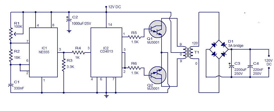
This is a simple circuit designed to convert 12V DC to 120V DC. The circuit comprises two main phases: the inverter stage and the rectifier and filter stage. The NE555 integrated circuit (IC1) is configured as an astable multivibrator,...
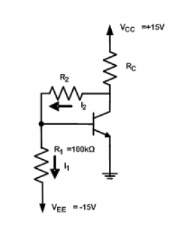
A circuit diagram has been provided for analysis, with the objective of calculating the values of resistors R2 and RC. The circuit is designed to operate at the Q-point with the following parameters: VCE = 5V, VBE = 0.7V,...
A simple thermostat circuit that can control a relay to supply power to a small space heater through the relay contacts. The relay contacts must be rated above the current requirements for the heater. Temperature changes are detected by...
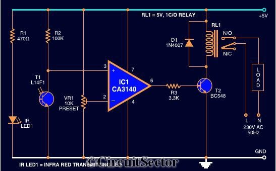
The circuit diagram presented is a highly sensitive wireless relay switch designed to control home appliances such as flush systems and hand dryers. This wireless switch operates without the need for a remote control. It functions by simply moving...
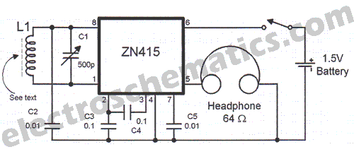
There are instances when a radio station can be found, and other times when no stations are detectable. The primary issue while tuning appears to be that any movement of the hands or body, such as releasing the tuning...