
Lc Tuned Amplifiers Circuit
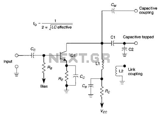
The tuned LC amplifier is a fundamental circuit used in various applications, including radio frequency (RF) amplification and signal processing. It consists of an inductor (L) and a capacitor (C) arranged in a resonant configuration, allowing it to selectively amplify signals at a specific frequency determined by the LC values.
The three output coupling methods provide flexibility in interfacing the amplifier with different circuit stages or loads:
1. **Capacitive Coupling Output**: This method involves using a capacitor to connect the output of the amplifier to the subsequent stage. The capacitor blocks any DC component while allowing AC signals to pass through, ensuring that the amplifier can effectively transmit the amplified signal without affecting the biasing of the next stage. This is particularly useful in applications where DC isolation is required.
2. **Capacitive Tapped Output**: In this configuration, a capacitor is tapped at a specific point in the amplifier circuit, allowing for a portion of the amplified signal to be extracted without affecting the overall operation of the amplifier. This method is advantageous for applications that require a specific signal level or for creating multiple output paths from a single amplifier stage.
3. **Link-Coupled Output**: This coupling method employs a transformer or a similar inductive link to transfer the amplified signal to the next stage. Link coupling is beneficial for impedance matching, as it can help maximize power transfer between stages. It also provides additional isolation and can enhance the frequency response of the overall system.
In summary, the basic tuned LC amplifier's versatility and the variety of output coupling methods available make it suitable for diverse applications in electronic circuits, particularly in RF and audio systems. Each coupling method offers unique advantages, allowing designers to select the most appropriate configuration based on specific requirements and constraints. This basic tuned LC amplifier can be used with three output coupling methods. They are capac-itive coupling output, capacitive tapped output, or link-coupled output. 🔗 External reference
Related Circuits
Cooling an instrument or device can enhance the signal-to-noise ratio (SNR) and extend the product's lifespan. For instance, the dark-and-noise signal of an infrared detector's output at room temperature can be significantly reduced when cooled. A custom cooling device...

This electronic circuit, based on the CD4017 and logic gates, activates a relay when four keys are pressed in the correct sequence, returning to the initial state afterward. The circuit utilizes the CD4017 decade counter, which is designed to count...
This article outlines the construction of a simple microcontroller-based delay circuit designed for photographic applications such as drop or high-speed photography. It can control the trigger lag of cameras and flash units, generate periodic trigger pulses, or manage magnetic...
This sound effects circuit is designed to function as a signal distorter. When utilized with an electric guitar, it enables the creation of unique sound effects. The sound effects circuit operates by manipulating the input audio signal from the electric...
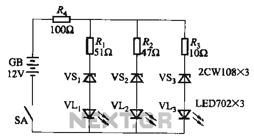
When the supply voltage falls below 10.2V, the yellow light-emitting diode (LED) VLi illuminates, indicating that the storage pool can no longer continue to discharge. Additionally, when the voltage exceeds 16.2V, the yellow, green, and red light-emitting diodes (LEDs)...
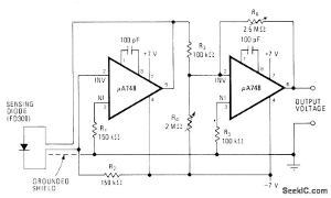
The following circuit illustrates a fully linear diode sensor circuit diagram. This circuit is based on the A748 integrated circuit (IC). Features include the use of an operational amplifier (op-amp). The fully linear diode sensor circuit utilizes the A748 IC...