
5V supply

RCH and diode D4 are used to trickle charge the battery at approximately 1.2 mA. When the 12-V supply is removed, resistor R1 and capacitor C1 initially keep T1 switched on. At this point, D3 becomes forward biased, allowing T1's drain current to flow through Rb, D3, and T2 from the battery. This action turns T2 on, permitting the load circuitry to draw current from the battery via D6 and the 5-V regulator. After a few seconds, capacitor C1 discharges through R1, causing the gate-source voltage (Vgs) to fall below the threshold for the FET, thus switching T1 off. Consequently, there is no longer a path for base current to T2, resulting in T2 also switching off and isolating the battery.
The circuit operates by utilizing a combination of diodes, resistors, and transistors to manage power supply transitions effectively. The presence of the 12-V mains supply enables the circuit to maintain the necessary voltage levels for proper operation of the microprocessor system. During brownouts, the circuit seamlessly transitions to battery power, ensuring continuous operation without interruption. The trickle charging mechanism ensures that the battery remains charged and ready for use when needed, while the design minimizes the risk of over-discharge by isolating the battery once the primary supply is restored. This arrangement provides a cost-effective solution for protecting sensitive electronic systems from temporary power outages.This circuit protects microprocessor systems from "brownouts" without the expense of an uninterruptible power supply. Designed around a small 9-V nickel cadmium battery the circuit continues to provide a constant 5-V output during brownouts of up to a few seconds.
Load currents of up to 500 mA may be drawn using the components shown. With this mains-derived supply present, D5 is forward biased so that the stabilized supply powers the 5-V regulator and hence the circuitry to be protected. FET Tj is held on by Dl, its drain current being provided from the dc supply via Rb and D2. Diode D3 is reverse-biased so that T2 is off, and the battery is isolated from D6. RCH and D4 serve to trickle charge the battery with approximately 1.2 mA. When the 12-V supply is removed, Rl and Cl initially keep Tl switched on. D3 is now forward biased, so that Tl drain current is drawn via Rb, D3 and T2 from the battery. This switches T2 on, allowing the load circuitry to draw current from the battery via D6 and the 5-V regulator. After a few seconds Cl has discharged (via Rl) such that Vgs falls below the threshold value for the FET, and Tl switches off.
There is then no path for T2 base current, so that it also switches off, isolating the battery.
Related Circuits
This dual polarity power supply is easy to build, requires few parts, and is adjustable from 0-15 volts. It is great for powering op amp circuits, as well as other circuits that require a dual supply voltage. The described dual...
Preamps may in some cases use a simple regulator, with the supplies taken from the main amp power supply. This can be a problem if the main amp is of very high power, as the supply voltage will be...
The filter consisting of resistors R1, R2, and capacitor C1 integrates the PWM waveform. The purpose of the operational amplifier appears to be that of a non-inverting amplifier, with the gain determined by resistors R6 and R7. However, the...
When the infrared receiver tube PH302 receives a signal from the remote control, the CX20106A selected frequency amplifier outputs a low-frequency signal. The low-level signal charges capacitor C through diodes D and R, causing the negative side potential of...
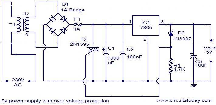
For circuits using TTL ICs, the supply voltage is a significant concern, as even a slight increase from the rated 5V can damage the IC. Relying solely on fuses is insufficient since a fuse may take several milliseconds to...
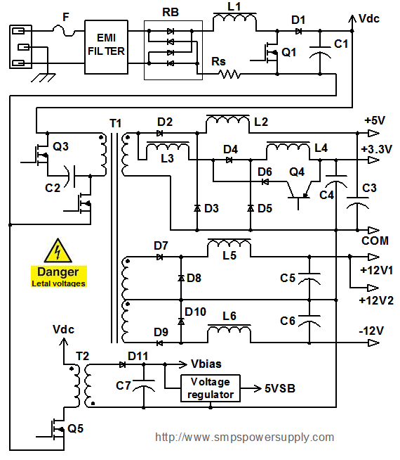
All electronic systems and equipment, regardless of their size or function, share a common requirement: a power supply unit (PSU) that converts input voltage into suitable voltage levels for their circuits. The most prevalent type of PSU today is...