
Homemade TV remote control off electrical power supply circuit
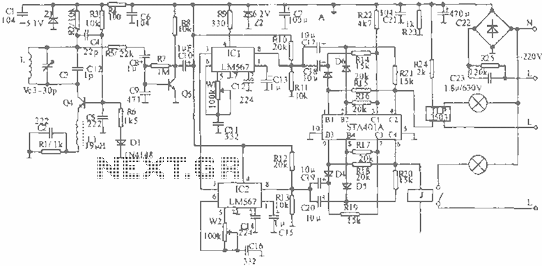
The circuit operates based on an infrared remote control system, utilizing the PH302 infrared receiver to detect signals emitted from the remote. Upon receiving a signal, the CX20106A amplifier processes the input, amplifying the low-frequency signal to a level suitable for further processing. The output from the amplifier is directed to a capacitor, denoted as C, which plays a crucial role in the timing and control of the relay mechanism.
Diodes D and R are integral components that facilitate the charging of capacitor C. As the capacitor charges, the voltage across its terminals rises until it reaches a threshold of 1/3 Vcc. This threshold is significant as it is the point at which the 555 timer, configured in monostable mode, triggers a discharge cycle. The discharge effectively activates the relay, which is responsible for controlling the power supply to a connected load.
The relay operates under a self-locking mechanism once switch S1 is engaged. This means that once the relay is activated, it remains in the on state until power is removed, allowing for continuous operation without the need for constant input from the remote control. The sensitivity of the RC circuit can be fine-tuned to adjust the response time of the system, typically set within a range of 3-5 seconds for optimal performance. This ensures that the system can reliably respond to user commands while preventing accidental activation.
Overall, this circuit design exemplifies a practical application of infrared communication and relay control, suitable for various electronic projects requiring remote operation and automated power management.When the infrared receiver tube PH302 receives a signal from the remote control, the CX20106A selected frequency amplifier output a low-frequency signal, the low-level signal by the D and R charges C, so C negative side potential falls below 1 / 3Vcc , .png">555 circuit discharge cutoff relay shock release, cut off the power supply. RC circuit sensitivity can be set to the action, press the remote control is generally 3-5 seconds. Press S1 relay circuit namely self-locking when powered on.
Related Circuits
A novel supply voltage monitor which uses a LED to show the status of a power supply. This simple and slightly odd circuit can clearly show the level of the supply voltage (in a larger device): as long as...
This is a three-band equalizer circuit, specifically a tone control circuit that utilizes a single operational amplifier (op-amp) and features three adjustable frequency ranges: bass, midrange, and treble. The three-band equalizer circuit employs an operational amplifier to achieve tone control...
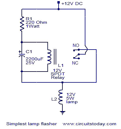
This is a simple lamp flasher circuit that utilizes only three components (a capacitor, a relay, and a resistor) in addition to the lamp. The operation of the circuit is straightforward. When power is turned on, the capacitor C1...
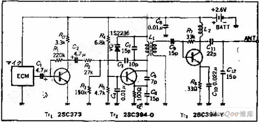
The circuit functions as a frequency modulation (FM) transmitter that operates within the 76 to 90 MHz FM radio band, commonly referred to as a wireless microphone. It receives signals through an FM radio receiver. The circuit is capable...
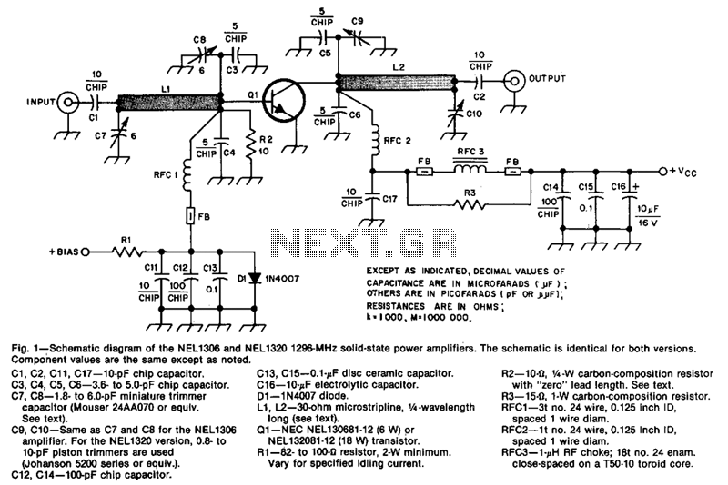
The design incorporates 30-ohm, 1/4 microstrip lines on the input and output. Capacitors C3, C4, C7, and C8, along with inductor L1, form a pi network that matches the low input impedance of the device to 50 ohms. Capacitors...
Figure 14-41 illustrates a multivibrator circuit utilizing a 555 timer alongside various capacitive and resistive components. The oscillation frequency is determined by the values of Ra, R16, and C3, following the formula f = 1.44 / ((Ra + 2R16)...