
5W 80M Cw Transceiver
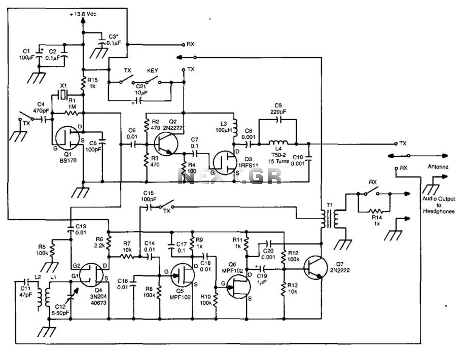
The transceiver circuit is designed to facilitate efficient communication by integrating a three-stage transmitter and a direct-conversion receiver. The transmitter's oscillator, Q1, plays a pivotal role in generating the RF signal, with its frequency being precisely controlled by crystal X1. This crystal not only stabilizes the transmitter's frequency but also acts as the local oscillator for the receiver, ensuring that both sections of the transceiver operate in harmony.
Buffer transistor Q2 is responsible for driving the final amplifier, Q3, which is capable of delivering an output power of around 5 watts. This output is sufficient for effective communication over a variety of distances. The B+ lead, which supplies power to these critical stages, is keyed to prevent unwanted transmission and to ensure that the circuit operates only when intended.
The receiver section is comprised of a mixer (Q4) that combines the incoming RF signal with the local oscillator signal from X1, effectively down-converting the frequency. The subsequent high-gain amplifiers, Q5, Q6, and Q7, amplify the audio signal extracted from the mixer. The output from Q7 provides the audio signal that can be further processed or sent to a speaker for audible output.
In the transmit mode, Q5, Q6, and Q7 are configured to function as a sidetone oscillator, allowing the operator to hear their own transmitted signal, which is crucial for ensuring clarity and proper modulation during transmission. The system incorporates a 6PDT switch to facilitate seamless switching between transmit and receive modes, enhancing the usability of the transceiver in various operational scenarios. This design emphasizes reliability and performance, making it suitable for a range of communication applications. This transceiver has a 3-stage transmitter and a direct-conversion receiver. Ql is the transmitter"s oscillator, an d the frequency is controlled by XI, which also serves as the receiver local oscillator. Buffer Q2 drives final amplifier Q3 to about 5 W output. The B+ lead to these stages is keyed. The receiver consists of mixer Q4 followed by high gain amplifiers Q5/Q6/Q7. The audio signal appears at the secondary of Q7. In the transmit mode, Q5/Q6/Q7 serve as a sidetone oscillator. A 6PDT switch is required for the T/R switching. 🔗 External reference
Related Circuits
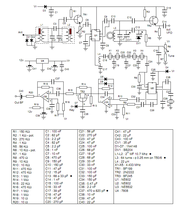
This project describes a little QRP transceiver full legal power (5 W at 12 V) for the 40 meters band. The RIG may be built in a gradual manner; in fact, it is divided into two main modules, or...
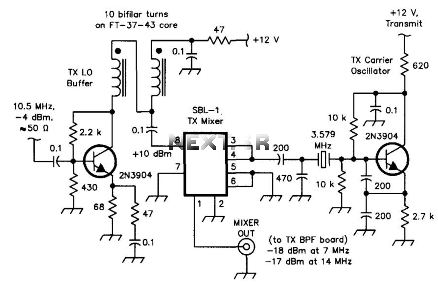
The transceiver mixer and carrier oscillator in the band-imaging (7- and 14-MHz) CW transceiver. Careful selection of drive levels and the use of a spectrally clean carrier oscillator ensure low spurious-signal content in the transmitter output. This transceiver mixer...
This is a 3-W, single-circuit board, VFO-controlled CW transceiver for 40 or 30 meters, featuring a direct-conversion receiver with audio filtering, Receiver Incremental Tuning (RIT), and speaker level audio volume. The transmit frequency is generated by Q1 and its...
This 80M receiver design incorporates the necessary switching mechanisms to enable the SSB filter and first intermediate frequency (I.F.) amplifier to function for transmission purposes. The receiver stages, from the radio frequency (R.F.) input to the speaker output, will...
A few weeks ago, Jason NT7S mentioned the ZL2BMI DSB transceiver as a rig that might be of interest for building. He was correct; it had been seen in SPRAT, but for some reason, it had not been seriously...
The choice of intermediate frequency (IF) is typically influenced by the availability of filters with the desired characteristics. For communication receivers or transceivers, the requirements for the main selective element are quite stringent, and two primary types of filters...