
80M

The 80M receiver design is an intricate assembly of various components that work cohesively to achieve effective signal processing for both receiving and transmitting. The use of a bandpass filter is crucial in maintaining the integrity of the signals by minimizing unwanted frequencies, especially in environments where strong VHF signals may interfere. The hand-wound inductors on TOKO 10K formers exemplify a practical approach to achieving desired inductance values, emphasizing the importance of precise calculations in RF design.
The mixer circuit, utilizing high-speed switching diodes, provides versatility in performance, allowing for substitutions with Schottky diodes to enhance efficiency. The attention to proper termination at the I.F. port is vital in preventing signal degradation and ensuring optimal mixer operation. This design also highlights the significance of using ferrite toroids for transformer winding, which contributes to improved magnetic coupling and overall circuit performance.
The post-mixer amplifier's choice of a grounded gate JFET configuration ensures low noise and high gain, critical parameters in RF applications. The ability to switch crystals for different frequencies reflects the design's adaptability, catering to various operational needs. The construction method employed—using the PCB's copper side—demonstrates a creative and resourceful approach to building RF circuits, emphasizing functionality over aesthetics.
Overall, this 80M receiver design serves as an exemplary model of RF engineering, integrating theoretical principles with practical application, and providing a robust solution for amateur radio enthusiasts and professionals alike.This 80M receiver design includes the necessary switching to allow the SSB filter and first I. F. amplifier to be used for transmitting. The receiver stages from R. F. input to speaker output will be described in detail below. This type of band pass filter gives very good attenuation at frequencies that are higher than the passband. This is desirabl e because diode dbm`s are very prone to harmonic mixing. This filter should keep out strong VHF signals. The good H. F. rejection of this filter will also reduce the possibility of I. F. breakthrough. The 10 microHenry inductors were hand wound on TOKO 10K coil formers. I used 25 turns of thin copper wire. To calculate the inductance of a home brew coil on a toko 10K former, use the following formula. For best results, use a high-level DBM. Mixers that have very good strong signal performance require +17 to +23dBm of local oscillator drive. Unfortunately, such mixers are very expensive. It is not difficult to build a home made mixer with similar performance. The mixer above uses a ring of four 1N914 high speed switching diodes. The switching diodes can be replaced with proper Schottky mixer diodes like the BA481. With 3. 7MHz on the R. F. port, 11. 5MHz on the L. O. port and a 7. 8MHz I. F, the 1N914`s seem to be just as good. The transformers were wound on ferrite toroids. I used eleven turns, trifilar wound on ferrite toroids. See the receiver section of the SSB transceiver project rx. html for details. Local oscillator injection is +23dBm. After the 3dB attenuator pad, the local oscillator power is +20 dBm (100mW. ) To get the best performance from a dbm, all ports should be properly terminated. It is particularly important that the I. F. port is properly terminated. The diplexer between the mixer I. F. port and the post mixer amplifier, ensures that the mixer has a 50 Ohm termination at all frequencies.
The reactance of L and C should be 50 Ohms at the I. F. frequency. The values at the top of the page are for a 7. 8MHz I. F. The 5. 02 microHenry inductors are: 18 turns on a Toko 10K former. Two capacitors are connected in parallel to get the required C of 408pF. The post mixer amplifier is a standard grounded gate J-FET amplifier. I used a J113 FET. I haven`t tried one, but the 2SK125 should be a suitable replacement. The output transformer is chosen to match the I. F. frequency. I used an 18 turn primary and 4 turn secondary, on a Toko 10K former. The C. I. O. is a standard, common collector, Colpitts oscillator. I used a pair of 2SC1675 transistors. A couple of 2N2222`s should work just as well. The crystal (7. 7985MHz) is in a socket. I can change to USB by changing the crystal. The circuit was built on the copper side of some PCB. It gives a whole new meaning to the term "Ugly Construction. " The voltage at the source of the second I. F. amp. is used to drive the s-meter. Use the 1K pot to zero the meter. Use the100K pot to set the maximum meter deflection, when receiving a very strong signal. L is 16 turns on a 0. 5in ceramic former (section of old 1KW electric heater element. ) Try using 20 turns, then adjust the tapping point until the oscillator is running at 11. 5MHz. The fet`s are J113`s. The transistor is a 2N2222A. 🔗 External reference
Related Circuits
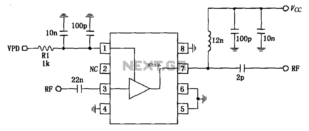
The circuit is based on an 880 MHz RF2347 low noise amplifier application. The radio frequency (RF) signal enters through input pin 3, and after amplification, the output is available at pin 7. The amplifier is directly coupled to...
A few weeks ago, Jason NT7S mentioned the ZL2BMI DSB transceiver as a rig that might be of interest for building. He was correct; it had been seen in SPRAT, but for some reason, it had not been seriously...
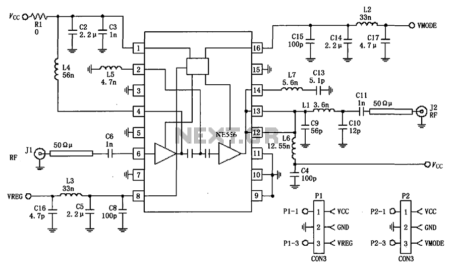
The circuit depicted in the figure is a 380MHz RF2175 linear amplifier application circuit. The radio frequency (RF) signal is input from pin 6 and is processed through a preamplifier, followed by a final power amplifier stage. The output...
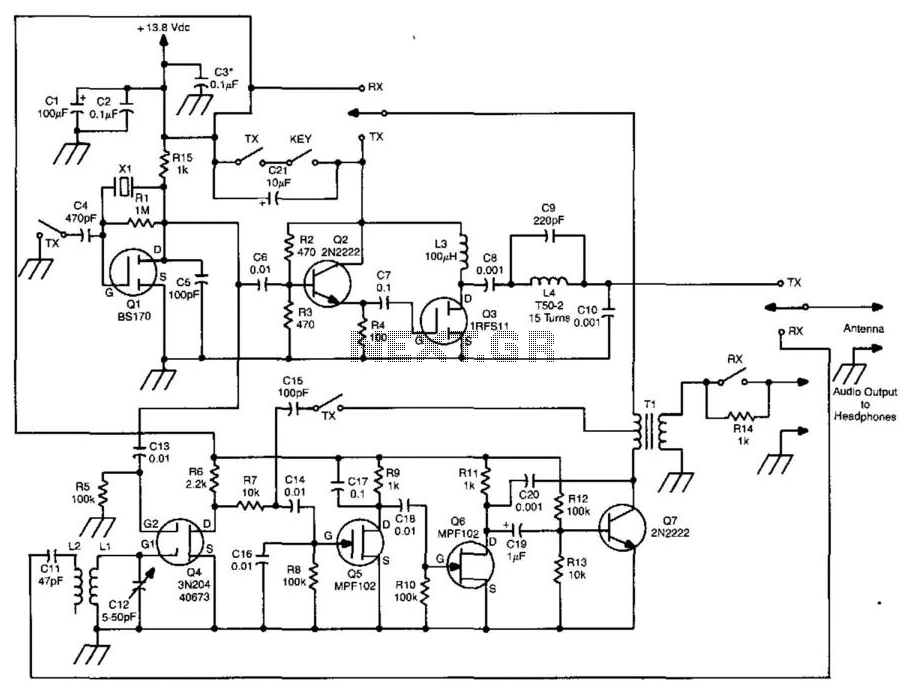
This transceiver features a three-stage transmitter and a direct-conversion receiver. The oscillator for the transmitter is controlled by Q1, with the frequency regulated by X1, which also functions as the local oscillator for the receiver. Buffer Q2 drives the...
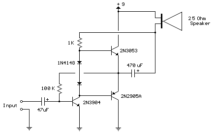
This circuit is similar to the one above but uses positive feedback to get a little more amplitude to the speaker. I copied it from a small 5 transistor radio that uses a 25 ohm speaker. In the circuit...
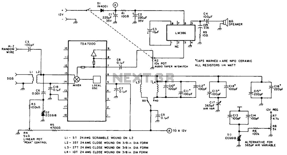
This direct-conversion receiver utilizes a TDA7000 integrated circuit (IC) and incorporates an LM386 audio amplifier. The TDA7000 serves as the mixer and local oscillator (L.O.) section. The frequency control can be achieved using either an air variable capacitor or...