
Positive Voltage Reference Circuit

The described circuit is engineered to maintain high precision and stability across a wide temperature spectrum, which is particularly important in environments where temperature fluctuations can affect performance. The dependency of IZ on V+ highlights the importance of a stable power supply to ensure consistent operation. The selection of resistors R1 through R4 is critical; these components are carefully chosen to optimize the current IZ, thereby minimizing the temperature coefficient. This ensures that variations in temperature do not significantly affect the circuit's output.
The compensation for unity gain operation is essential for maintaining stability, particularly in feedback configurations. In scenarios where large capacitive loads are expected, overcompensation is advised to prevent oscillations and ensure reliable performance. Bypassing the amplifier input is a technique employed to further reduce output noise, which can be particularly beneficial in sensitive applications where signal integrity is paramount.
The use of a single power supply simplifies the circuit design but introduces challenges related to the common mode range of the amplifier. It is crucial to select an amplifier that can handle the expected common mode voltages without distortion or loss of performance. In cases where the amplifier's common mode range is insufficient, implementing a dual power supply can provide the necessary headroom to accommodate the input signal range.
The LH101 amplifier is noted for its capability to operate effectively within the specified power supply configuration, making it a suitable choice for this circuit. Its common mode range, extending from V+ down to approximately 2 volts above V-, allows for flexibility in design while ensuring that the amplifier can handle the input signals without compromising performance. Overall, careful consideration of component selection and configuration is essential to achieve the desired precision and reliability in this circuit design.The circuit are suited for high precision extended temperature service if V+ is reasonably constant since IZ is dependent on V+. R1, R2, R3, and R4 are chosen to provide the proper IZ for minimum T. C. and to minimize errors due to Ibias. The circuits shown should both be compensated for unity gain operation or, if large capacitive loads are expect
ed, should be overcompensated. Output noise may be reduced in both circuits by bypassing the amplifier input. Here is a schematic drawing: The circuits shown employ a single power supply, this requires that common mode range be considered in choosing an amplifier for these applications. If the common mode range requirements are in excess of the capability of the amplifier, two power supplies may be used.
The LH101 may be used with a single power supply since the common mode range is from V+ to within approximately 2 volts of V-. 🔗 External reference
Related Circuits
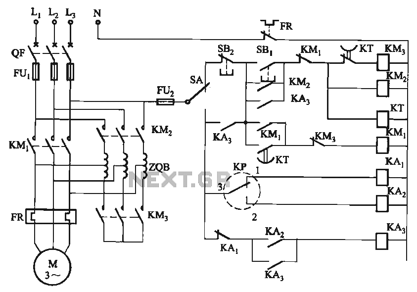
The circuit utilizes a motor auto-voltage transformer for starting. The motor auto-voltage transformer start circuit is designed to provide a controlled method for initiating the operation of an electric motor. This type of circuit is particularly beneficial in applications where...
Here is the schematic diagram for a 20 Watt driver. I developed this circuit in 1985, and used it to build a lamp that found much use both as camping light and as emergency light during the then-frequent power...
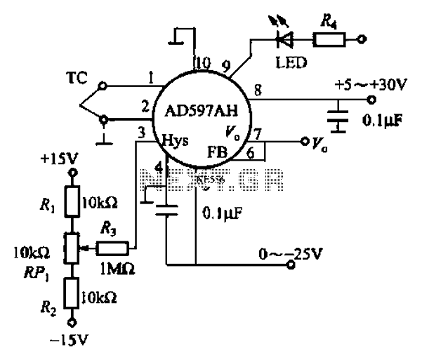
An automatic electric furnace temperature controller is illustrated. The closed circuit consists of a temperature detection output control loop; as the temperature increases, the output voltage rises until it reaches a preset temperature value, at which point the output...
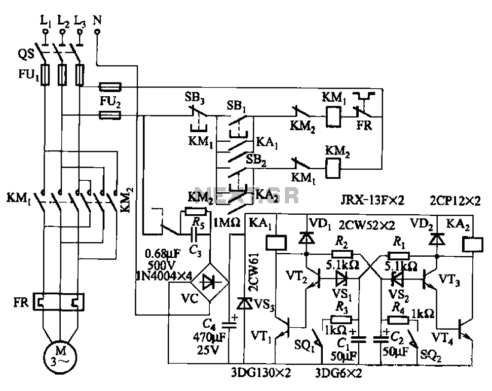
The circuit illustrated in Figure 3-72 employs a deformable bistable reversing motor control mechanism that automatically initiates and halts operation during a user-defined time delay. This feature is designed to safeguard the motor from potential impacts during the reversing...
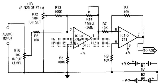
This simple general-purpose driver for an analog/digital converter uses two 741 IC devices with adjustable gain and offset. Other op-amps might be substituted, but some circuit adjustments might be needed. The circuit consists of two operational amplifiers (op-amps) from the...
Modify a zapper circuit (similar to the Hulda Clark Zapper) to produce two different frequencies. One switch should be used to set the pulse to 15Hz, and another switch to set it to 30Hz. The nominal frequency for this...