
5x10 vu meter
The LM3915 VU meter is a popular integrated circuit used for visual audio level indication. In this circuit, it is essential to implement band-pass filters to isolate specific frequency ranges of audio signals. The design aims to create five distinct channels, each corresponding to a specific frequency band, which will collectively form a spectrum analyzer.
To design the band-pass filters, the center frequencies have been chosen at 62 Hz, 250 Hz, 1 kHz, 4 kHz, and 16 kHz. Each filter's bandwidth can be adjusted by selecting appropriate resistor and capacitor values. The cutoff frequency for each filter can be calculated using the standard formula for a second-order band-pass filter, which defines the relationship between resistance (R), capacitance (C), and frequency (Fo). The designer must determine the resistance value that the LM3915 will present to the filter circuit, as this is crucial for accurate calculations.
The mid-band gain (Ao) of the filters is significant as it amplifies the signal within the passband, allowing for a more pronounced visual indication on the VU meters. To widen the frequency bands, one approach could involve adjusting the quality factor (Q) of the filters, which influences the bandwidth. A lower Q value results in a wider bandwidth, thus capturing a larger portion of the audio spectrum.
It is also important to note that these filters will not produce unity gain; therefore, appropriate gain settings must be established to ensure that the output levels are suitable for the LM3915 input. This aspect emphasizes the need for careful calibration to achieve the desired performance of the spectrum analyzer.
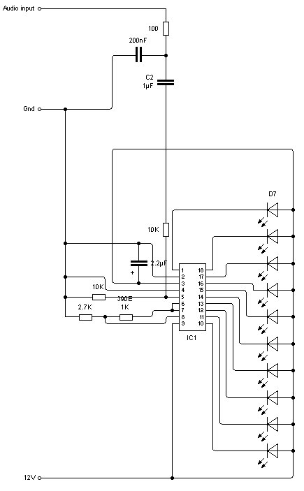
In conclusion, the project involves creating a multi-channel spectrum analyzer using LM3915 VU meters and band-pass filters. By selecting the right component values and understanding the relationship between frequency, resistance, and capacitance, the designer can successfully implement a functional and visually effective audio spectrum analysis system.A nice schematic for an lm3915 VU meter. I have attempted to create a band pass filter in order to only input part of the audio frequency spectrum into the VU meter circuit, this is becuase I plan to have 5 of these circuits to make a spectrum analyser or w/e its called. I have not been able to work out the value for the capacitor marked C2 in the diagram because I dont know what resistance the lm3915 circuit will produce and therefore I cannot use the formula of 1/(2piRC) = cuttoff frequency. Also note that I may well be in slightly over my head with this since I have not touched electronics since about two and a half years ago when I did electronics GCSE.
I will attach the schematic of the spec analyzer I designed and built for my stereo. You can use the filter section values. Each one is a bandpass filter centered on the frequency listed by it. The filters are shown on the page 2 schematic below. I believe on page 1, I have the explanation and formulas for calculating the frequency for the bandpass center frequency (Fo). Also "Ao" is the midband gain of the filter. So if I wanted to split it into 5 bands i would just use filters with Fo of 62, 250, 1K, 4K and 16K. But how do I make the bands wider so that I am not missing chunks of the spectrum Or is that where the midband gain comes into it These are not unity gain filters, they have voltage gain.
take the 1K Hz filter: midband gain means if you put a 10mV (1 KHz) sine wave into it, you will get out a 1Khz sine wave whose amplitude is larger by the midband gain. So if I wanted to split it into 5 bands i would just use filters with Fo of 62, 250, 1K, 4K and 16K. But how do I make the bands wider so that I am not missing chunks of the spectrum Or is that where the midband gain comes into it Well I dont really know the difference so sorry for all the confusion, but isnt a spectrum analyser just a load of VU meters that each measure a part of the spectrum (or a VU meter hooked up to some sort of variable filter that can sweep through the spectrum).
🔗 External reference
Related Circuits
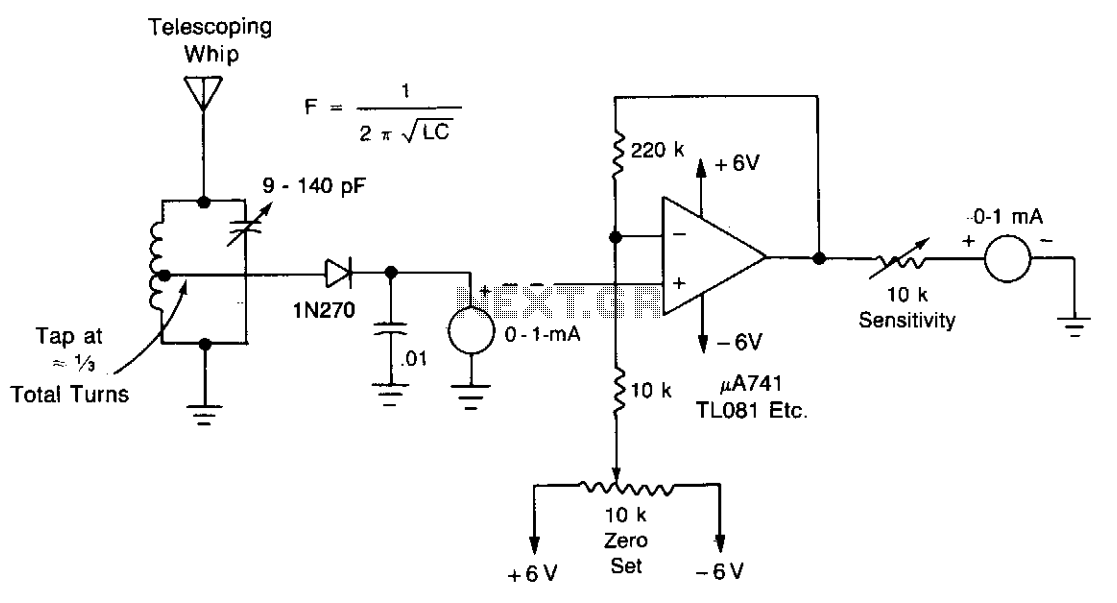
A field-strength meter with minimal components is presented here. For testing at greater distances, a DC amplifier can be added. It is recommended to use a single wire as the antenna. The field-strength meter is a simple yet effective device...
The RF signal is divided into two signals that are shifted 90 degrees out of phase (one at plus 45 degrees and one at minus 45 degrees). Both signals are then mixed to audio frequencies. The two audio signals...
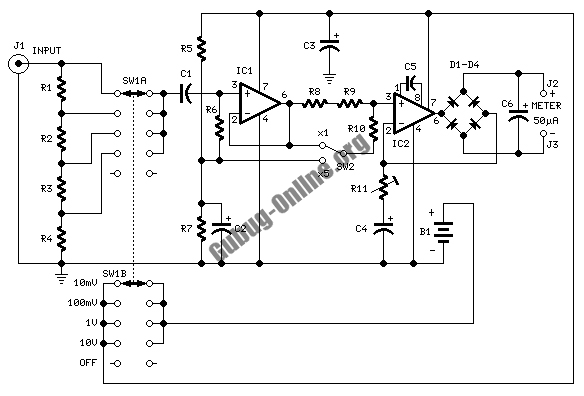
This design circuit is used to activate circuitry and an analog meter for sensitive DC current measurements. A subsequent inquiry raised the possibility of measuring AC microamperes, which inspired the idea for this circuit. The circuit is designed to facilitate...
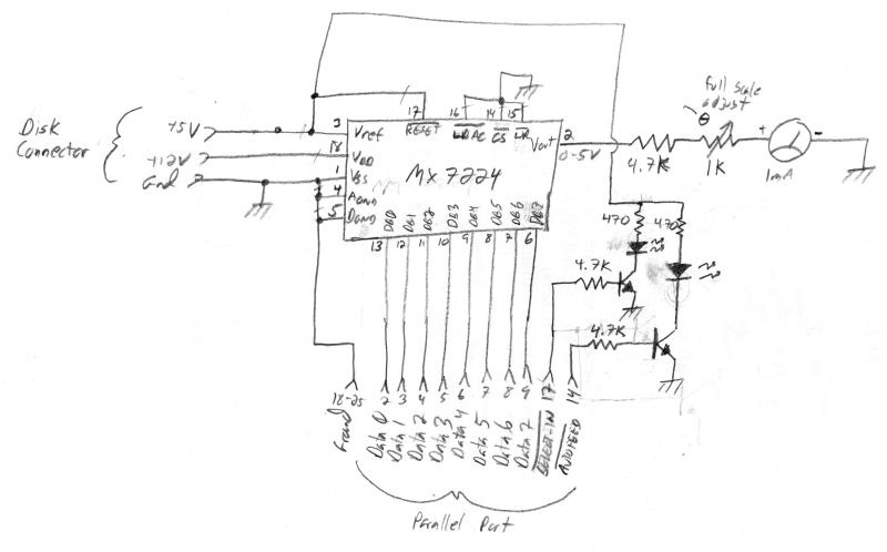
The meter was acquired from eBay and features a full-scale movement of 1 mA, already marked from 0 to 100. The original scale was removed, scanned, and modified to include "% NETWORK" markings using an image editor. The new...
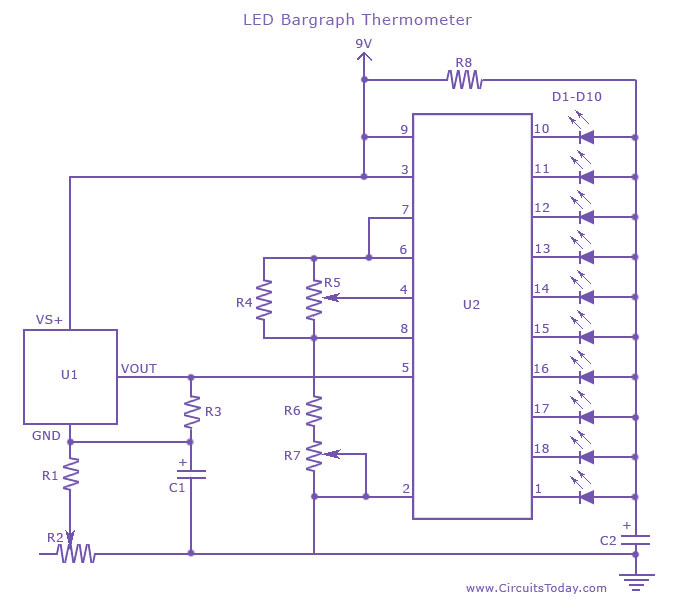
An LED thermometer that can function as a temperature sensor or temperature measurement circuit, utilizing the LM34 for Fahrenheit display or the LM35 for degree Celsius display. The LED thermometer circuit is designed to provide accurate temperature readings using either...
This indicator lets you see how much power an amplifier produces. The circuit uses an LM 3915, the logarithmic variation of the known IC LED VU Meter LM 3914. The circuit is connected directly to the speaker output of...