
Field-strength meter II
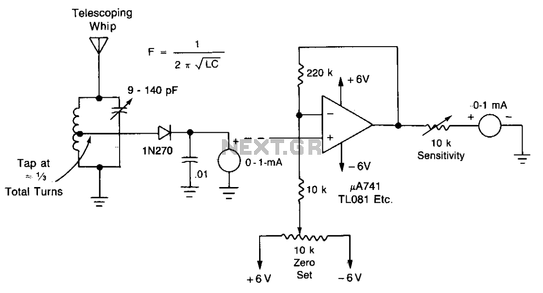
The field-strength meter is a simple yet effective device used to measure the strength of electromagnetic fields. The design emphasizes minimalism, relying on a limited number of components to achieve functionality. The core of the circuit typically includes a diode, which rectifies the incoming radio frequency signals, and an analog meter or LED indicator to display the signal strength.
To enhance the range of the field-strength meter, a DC amplifier can be integrated into the circuit. This amplifier will boost the signal received by the antenna, allowing for more accurate readings at greater distances. The amplifier can be configured using operational amplifiers (op-amps) or transistors, depending on the desired specifications and complexity of the design.
The use of a single wire as an antenna is a practical approach in this circuit. This wire acts as a simple monopole antenna, which is effective for receiving radio waves. The length of the wire can be adjusted to optimize the reception for specific frequency ranges.
In summary, the described field-strength meter is a versatile tool for electromagnetic field measurement, with the potential for increased range through the addition of a DC amplifier. The straightforward design and use of a single-wire antenna make it accessible for various applications in electronics and radio frequency testing."Minimum-parts" field-strength meter is shown here. For more distant testing, add the dc amplifier. Use a single wire for antenna. 🔗 External reference
Related Circuits
After completing the prototype and ensuring the sketch functions correctly, it is time to construct the circuit. The aim is not to provide a detailed explanation of how to create printed circuit boards, but rather to offer a general...
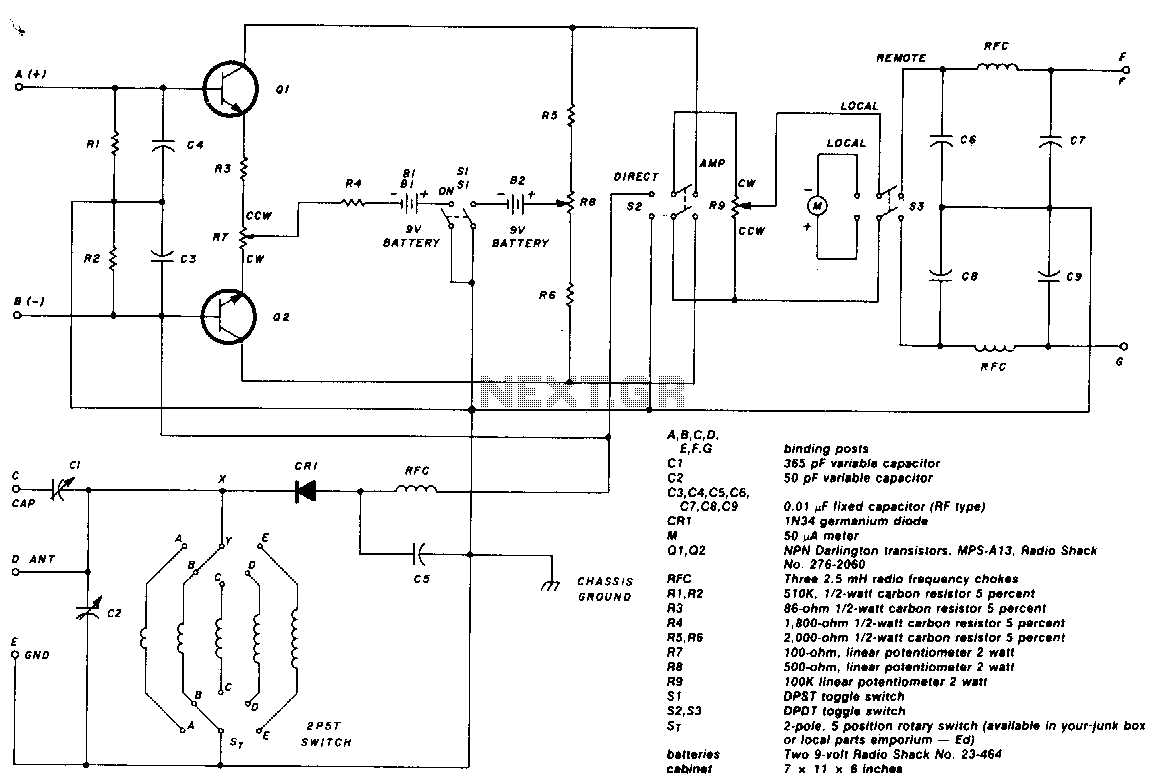
The two-pole, five-position switch, coils, and 365-pF variable capacitor cover a range from 1.5 to 30 MHz. The amplifier uses Darlington npn transistors whose high beta of 5000 provides high sensitivity, with SL used as the amplifier on/off switch....
A frequency meter can be utilized in speed sensors, tachometers, or any application that requires the measurement of repetitive signals. This frequency-to-voltage converter (FVC) is designed to facilitate the conversion process. The frequency meter is an essential instrument in various...
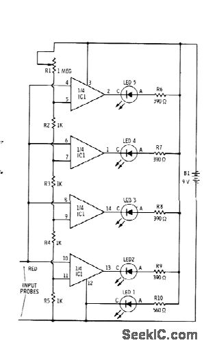
Sections of the RS339 quad comparator each drive an LED to indicate four different input voltage levels. LED 1 is connected to ground to serve as a zero indicator. The resistors depicted are intended for Radio Shack 276-041 red...
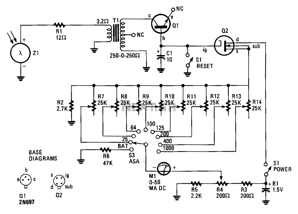
The circuit comprises an insulated-gate field-effect transistor (IGFET) labeled Q2 and a silicon photo cell designated Z1. Transformer T1, an audio-output type, is configured in reverse within the circuit. When a sudden flash from a photoflash unit is detected...
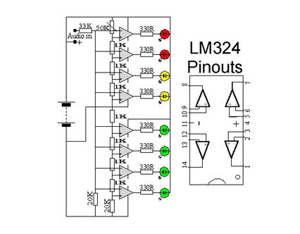
This circuit utilizes two quad op-amps to create an eight LED audio level meter. The op-amp employed in this circuit is the LM324, which is a widely available integrated circuit. The 1K resistors in the circuit are crucial for...