
6-12 Chanel TV Transmitter-Coupling
The 6-12 channel TV transmitter coupling circuit is essential for ensuring stable transmission across multiple channels. The circuit typically consists of several key components, including amplifiers, filters, and coupling capacitors, which work together to enhance signal quality and reduce interference.
In this configuration, the circuit may utilize a series of RF amplifiers to boost the signal strength before transmission. These amplifiers are critical for maintaining signal integrity, especially in environments with potential signal degradation. Additionally, the inclusion of bandpass filters helps to select the desired frequency range while attenuating unwanted frequencies, thus improving overall transmission clarity.
Coupling capacitors are also integral to this circuit, as they facilitate the connection between different stages of the circuit while blocking DC components. This allows for the effective transfer of AC signals, which is crucial for maintaining the quality of the transmitted signal.
The design should also consider impedance matching to ensure maximum power transfer and minimize signal reflections, which can lead to distortion. This can be achieved through the careful selection of component values and configurations.
Overall, the 6-12 channel TV transmitter coupling circuit is a sophisticated assembly that requires careful design and component selection to ensure reliable and high-quality television transmission across multiple channels.Description: This circuit shows about 6-12 Chanel TV Transmitter-Coupling Circuit Diagram. Features: used to stabilize the 10 P to work in the 6-12 channel .. 🔗 External reference
Related Circuits
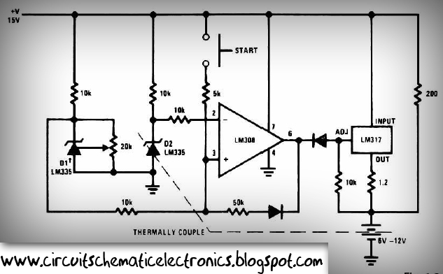
This circuit is designed for rapid battery charging. It is recommended for those who require a faster charger. The charger operates at a low temperature of 5 degrees Celsius. The input voltage is 15 volts DC, while the output...
A 40-watt fluorescent tube lamp or two 20-watt tubes in series will be driven by this circuit; however, this circuit will produce less brightness than usual, since... This circuit is designed to operate a 40-watt fluorescent tube lamp or two...
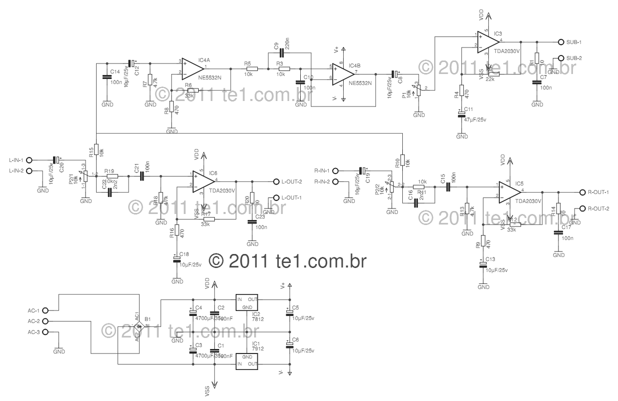
This circuit is a complete application for a 2.1 amplifier system, consisting of two satellite speakers powered by a TDA2030 and one subwoofer. This 2.1 system is commonly utilized in commercial applications as an amplifier for computers, enhancing audio...