
12V 6-12 Watt Fluorescent Tube (Neon) Lamp Inverter
 Lamp Inverter")
This circuit is designed to operate a 40-watt fluorescent tube lamp or two 20-watt tubes connected in series. The operation of fluorescent lamps involves the ionization of gas within the tube, which emits ultraviolet light that is subsequently converted to visible light by the phosphor coating inside the tube.
In this circuit configuration, the input voltage is typically rectified and regulated to ensure a stable current flow through the tubes. The circuit may include a ballast, which is a critical component that limits the current flowing through the fluorescent tubes, preventing them from drawing excessive current that could lead to overheating or failure.
The reduced brightness mentioned in the description can be attributed to several factors, including the type of ballast used, the voltage supplied to the circuit, and the overall efficiency of the circuit design. If an electronic ballast is utilized, it may provide better performance and efficiency compared to a magnetic ballast; however, if the circuit is designed with suboptimal components or configurations, it may result in lower light output than expected.
To achieve optimal performance, it is essential to ensure that the circuit is designed with appropriate ratings for the ballast and that the tubes are compatible with the circuit specifications. Additionally, the circuit should be protected against overcurrent conditions and have provisions for thermal management to enhance longevity and reliability.
Overall, careful consideration of the circuit design and component selection is necessary to ensure that the fluorescent tubes operate efficiently while providing adequate illumination.A 40 watt fluorescent tube lamp or two 20-watt tubes in series will be driven by this circuit but this circuit will produce less brightness than usual, since.. 🔗 External reference
Related Circuits
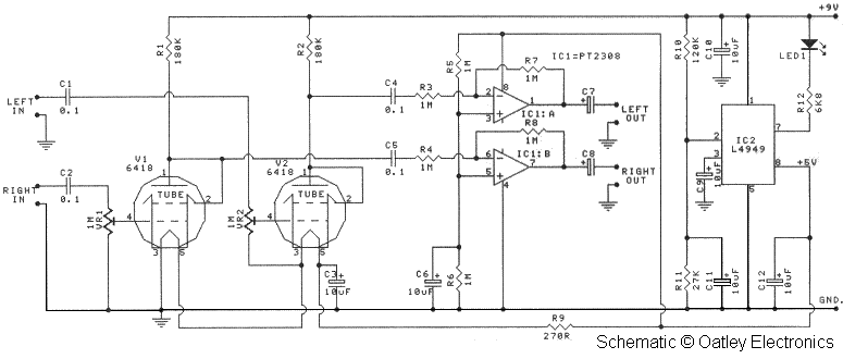
Oatley Electronics, located in New South Wales, Australia, offers several kits based on the Raytheon JAN 6418 sub-miniature valve (tube). The K272A Stereo Tube Preamplifier - Headphone Driver kit, priced at $27 AU, is one such kit. (Note: The...
This circuit functions as a low-frequency warning device. The output from the oscillator generates a square wave signal, which is utilized to operate lamps or small relays. The circuit alternately flashes two incandescent lamps. The low-frequency warning device circuit typically...
As an alternative to a bipolar transistor, a lamp flasher can be constructed using two power FETs. Similar to other flasher circuits, this circuit alternately switches the... The proposed lamp flasher circuit utilizes two power Field-Effect Transistors (FETs) to control...
The circuit is very simple and incorporates darlington output transistors that will provide more than enough output current than is needed to drive a 3-ohm speaker. The gain may be pre-set for a variety of input levels, making it...
The schematic circuit design is for a 250-watt output inverter. To increase the power of the circuit, additional Q7 and Q8 transistors can be added in parallel; each pair contributes an additional 250 watts. For instance, to achieve 750...
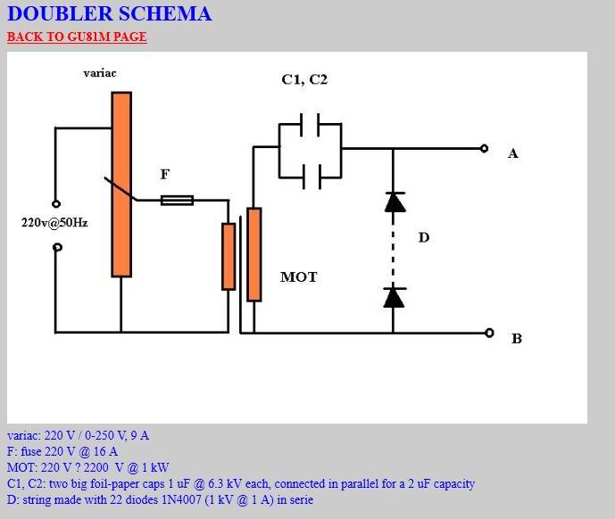
The coil has been enhanced with additional turns, necessitating an improvement in insulation. Epoxy was chosen as the insulating material, with an increased quantity applied over the soldered connections. To ensure the reliability and performance of the coil, the additional...