
6.5Mhz Vfo Circuit
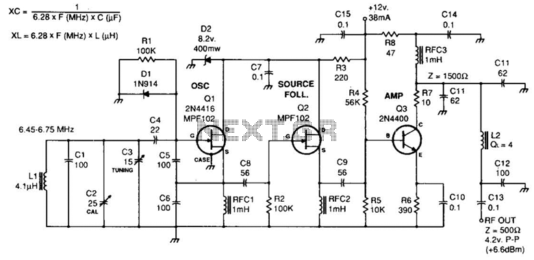
The circuit described incorporates fixed-value capacitors, specifically disc ceramic types, which are known for their stability and reliability in various electronic applications. Capacitors C1, C4, C5, C6, and C8 are categorized as NPO ceramic or polystyrene, materials that exhibit low dielectric loss and minimal capacitance change with temperature variations, making them suitable for high-frequency circuits.
Capacitor C2 serves as a 25-pF ceramic trimmer, allowing for fine-tuning of capacitance values to achieve desired circuit performance. Capacitor C3 is a 15-pF miniature air variable capacitor, providing adjustable capacitance which is beneficial in tuning applications, particularly in radio frequency (RF) circuits.
The resistors utilized in this schematic are rated at ¼ watt and are either carbon film or composition types, chosen for their stability and accuracy in current limiting and voltage division applications.
The RF chokes included in the design are miniature units from Mouser Electronics, specifically model No. 43LR103. These components are essential for suppressing high-frequency noise and preventing unwanted oscillations in the circuit.
Inductor L1 is constructed using 32 turns of #28 enamel wire wound on an Amidon Assoc. T50-6 (yellow) toroid. This toroidal inductor design minimizes electromagnetic interference and optimizes inductance, making it suitable for RF applications. Inductor L2 consists of 25 turns of #28 enamel wire on an Amidon FT-37-61 ferrite toroid, which is designed to enhance performance in higher frequency ranges due to its superior magnetic properties.
Overall, the schematic diagram of the Variable Frequency Oscillator (VFO) integrates these components effectively to create a stable and tunable oscillator circuit, essential for various RF applications. The choice of materials and component specifications reflects a design focused on achieving high performance and reliability in electronic circuit operations. Fixed-value capacitors are disc ceramics. CI, C4, C5, C6, and C8 are NPO ceramic or polystyrene. C2 is a 25-pF ceramic trimmer and C3 is a 15- pF miniature air variable capacitor. The resistors are -W carbon film or composition. The RF chokes are miniature Mouser Electronics No. 43LR103 units. For LI, use 32 turns of #28 enamel wire on an Amidon Assoc. T50-6 (yellow) toroid. L2 has 25 turns of #28 enamel wire on an Amidon Ft-37-61 ferrite toroid. Schematic diagram of the VFO. Fixed-value capacitors are disc ceramic. C1.C4, C5, C6, andC8areNP0 ceramic or polystyrene. C2 is a 25 pF ceramic trimmer and C3 is a 15 pF miniature air variable. Resistors are V* watt carbon film or composition. The RF chokes are miniature Mouser Electronics No. 43LR103units. For L1 use 32 turns of No. 28 enamel wire on an Amidon Assoc. T50-6 (yellow) toroid. L2 has 25 turns of No. 28 enamel wire on an Amidon FT-37-61 ferrite toroid. 🔗 External reference
Related Circuits
The Astable Multivibrator, which is generally used as a signal generator, is once again used here to generate the desired frequencies. It is an excellent example of the fact, how versatile simple basic electronic circuit can be. It seems...
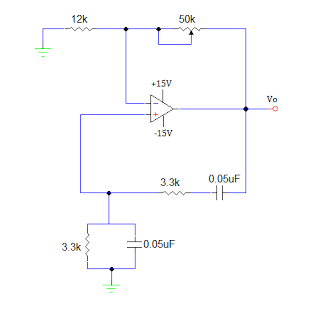
An operational amplifier-based sine wave generator circuit, commonly known as a Wien bridge oscillator, is recognized for its simplicity and stability. The Wien bridge oscillator connects the Wien bridge circuit between the amplifier's input and output terminals. The bridge...
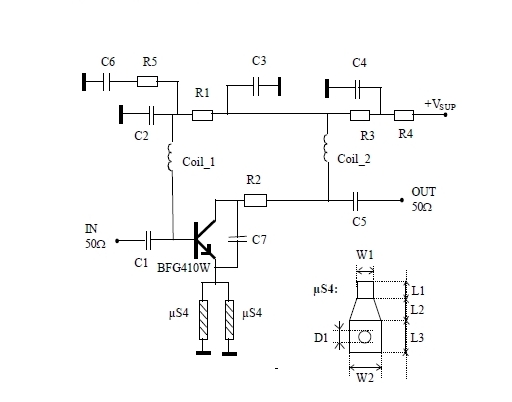
This 900 MHz amplifier circuit is constructed using the BFG480W transistor, which exhibits excellent linearity performance. As a result, the BFG480W is highly suitable for low-noise amplifiers (LNAs) that require high linearity. The 900 MHz amplifier circuit utilizing the BFG480W...

This simple circuit is designed to check transistors, allowing measurements down to 40 ohms across the collector-base or base-emitter junctions. It is also capable of testing output power transistors in amplifier circuits. The circuit operates with a 555 timer...
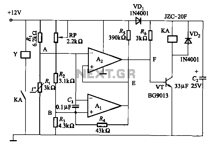
Electronic temperature control circuit for imported car air conditioners. It utilizes operational amplifiers A1 and A2, specifically the LM393 model. An adjustment potentiometer (RP) is included, allowing modification of the temperature range. The adjustment range includes a power temperature...
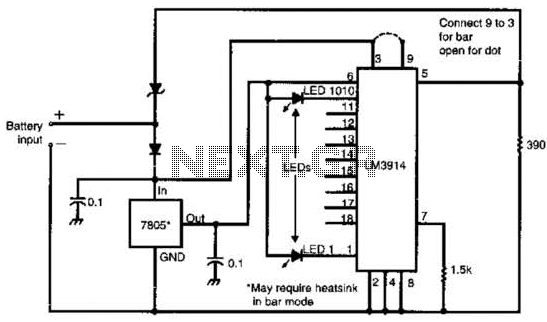
Many amateur receivers are equipped with an S meter that does not operate logarithmically. The proposed circuit is intended to enhance such receivers. Although integrated circuits like the CA3089 or CA3189 are not commonly used today, they play a...
Warning: include(partials/cookie-banner.php): Failed to open stream: Permission denied in /var/www/html/nextgr/view-circuit.php on line 713
Warning: include(): Failed opening 'partials/cookie-banner.php' for inclusion (include_path='.:/usr/share/php') in /var/www/html/nextgr/view-circuit.php on line 713