
in circuit transistor checker

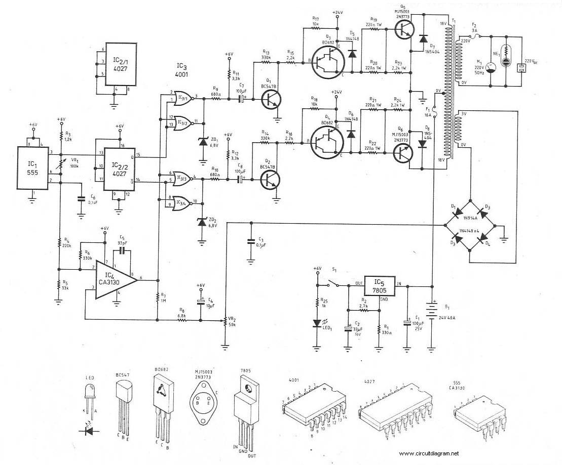
The circuit employs a 555 timer configured in astable mode, producing a square wave output at a frequency of 12 Hz. This output serves as the clock signal for the 4027 flip-flop, which functions to divide the frequency by two, yielding complementary outputs. The flip-flop's outputs are used to control two LEDs, providing a visual indication of the transistor's condition.
Resistor R3 is crucial for limiting the current flowing through the LEDs, preventing damage while ensuring adequate brightness. The arrangement of the LEDs allows for clear indication of the transistor type being tested: NPN or PNP. The current-limiting resistors R4 and R5 serve to bias the base of the transistor under test, ensuring that it operates within its specified parameters.
When a transistor is connected, its characteristics dictate the behavior of the LEDs. A functioning NPN transistor will allow current to flow through LED1, illuminating it, while a functioning PNP transistor will cause LED2 to light up. The circuit's design ensures that it can effectively diagnose the state of the transistor, providing immediate feedback on its functionality. If the transistor is open, the circuit will not complete, resulting in both LEDs flashing alternately, indicating that the transistor is not conducting. Conversely, if the transistor is shorted, it will create a direct path, preventing any LED from lighting.
This circuit is a practical tool for electronics enthusiasts and professionals, allowing for quick and efficient testing of transistor functionality in various applications, including audio amplifiers and signal processing circuits.This simple circuit has helped me out on many occasions. It is able to check transistors, in the circuit, down to 40 ohms across the collector-base or base-emitter junctions. It can also check the output power transistors on amplifier circuits. Circuit operation is as follows. The 555 timer ( IC1 ) is set up as a 12hz multi vibrator. The output on pin 3 drives the 4027 flip-flop ( IC2). This flip-flop divides the input frequency by two and delivers complementary voltage outputs to pin 15 and 14. The outputs are connected to LED1 and LED2 through the current limiting resistor R3. The LEDs are arranged so that when the polarity across the circuit is one way only one LED will light and when the polarity reverses the other LED will light, therefore when no transistor is connected to the tester the LEDs will alternately flash.
The IC2 outputs are also connected to resistors R4 and R5 with the junction of these two resistors connected to the base of the transistor being tested. With a good transistor connected to the tester, the transistor will turn on and produce a short across the LED pair.
If a good NPN transistor is connected then LED1 will flash by itself and if a good PNP transistor is connected then LED2 will flash by itself. If the transistor is open both LEDs will flash and if the transistor is shorted then neither LED will flash.
🔗 External reference
Related Circuits
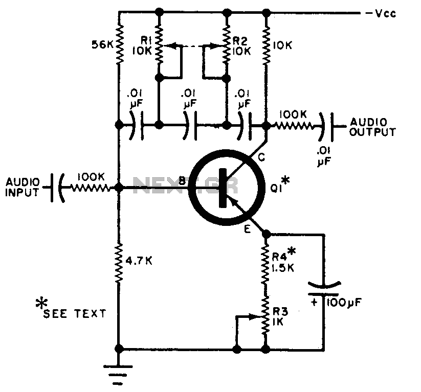
The circuit can be selectively tuned to two closely related tones. The selective frequency is determined by the values of the feedback circuit connected to the collector and base of Q1, which includes capacitors and resistors. When the specified...

This simple receiver AF amplifier can supply several hundred milliwatts to an 8-ohm speaker. The gain is approximately 200X. If high gain is not required, C2 can be removed, resulting in a gain of 20. R1 and C6 are...
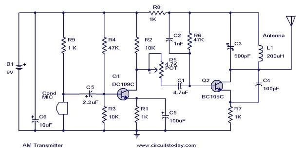
This document presents a circuit diagram of a simple AM transmitter that is capable of transmitting audio signals to a specified area. The circuit is designed with a limited power output to comply with FCC regulations while effectively producing...
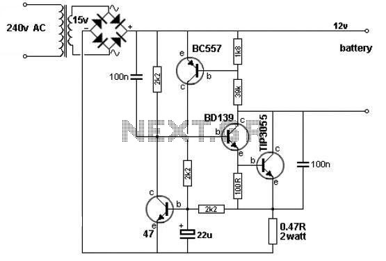
A simple 12V battery charger circuit can be designed using a TIP3055 power transistor to limit the current to the battery. The circuit turns off when the battery voltage reaches approximately 14V or if the current exceeds 2A. This...
This 555 timer circuit toggles a relay when a button is pressed. Pins 2 and 6, which are the threshold and trigger inputs, are maintained at half the supply voltage by two 10K resistors. When the output is high,...
This is the schematic diagram of a 300W power inverter circuit. The inverter utilizes the MJ15003 power transistor for final amplification. If the MJ15003 transistor is difficult to source, it can be replaced with a 2N3773. The inverter is...
Warning: include(partials/cookie-banner.php): Failed to open stream: Permission denied in /var/www/html/nextgr/view-circuit.php on line 713
Warning: include(): Failed opening 'partials/cookie-banner.php' for inclusion (include_path='.:/usr/share/php') in /var/www/html/nextgr/view-circuit.php on line 713