
Three temperature switch circuits

The electronic temperature control circuit is designed to regulate the temperature within imported car air conditioning systems effectively. The circuit employs two operational amplifiers, A1 and A2, which are configured to form a comparator setup using the LM393 integrated circuit. This IC is known for its low power consumption and high-speed performance, making it suitable for automotive applications where reliability is crucial.
The adjustment potentiometer (RP) facilitates user-defined settings for the desired temperature range. The operational amplifiers compare the voltage from the thermistor against a reference voltage set by the potentiometer. The thermistor has a negative temperature coefficient, meaning its resistance decreases as temperature increases. This characteristic allows the circuit to accurately monitor the ambient temperature and adjust the air conditioning system accordingly.
The specified temperature range allows for operational flexibility, with a power temperature setting adjustable between 6 and 18 degrees Celsius. The shutdown temperature is set at 15 degrees Celsius, providing a safety threshold to prevent the system from operating outside optimal conditions. The temperature differential of 3 degrees ensures that the system does not engage and disengage too frequently, enhancing the longevity of the components involved.
The use of the RR03-2 thermistor, with a resistance of 3k ohms at 25 degrees Celsius, is ideal for this application, providing the necessary sensitivity for accurate temperature readings. Alternatively, the MF51 thermistor can also be utilized, offering similar performance characteristics. The design of this circuit ensures that it can be integrated seamlessly into existing car air conditioning systems, enhancing user comfort through effective temperature regulation.Electronic temperature control circuit on an imported car air conditioners. Operational amplifier Ai, A2 using LM393. Adjustment potentiometer RP. Temperature range can be chan ged. Adjustment range: Power temperature 6 ~ 18, 3 ~ shutdown temperature 15 C, the temperature difference between the opening stop of 3. Negative temperature coefficient thermistor R. RR03-2 type can be used, 25 resistance is 3k, Q, or MF51 type.
Related Circuits
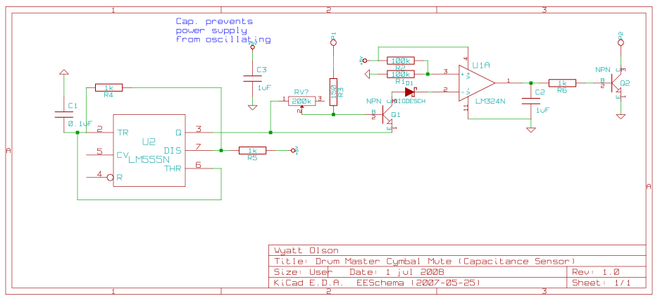
This page contains various small circuits created over time. Some circuits are trivial, while others are more complex, but all are intended to be useful for a variety of projects. Most include both the schematics and the source (KiCad)...
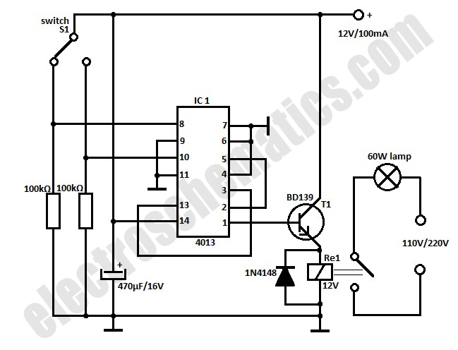
This automatic door light switch circuit activates a lamp when a door is opened and deactivates it when the door is closed again. The working principle of the circuit involves a sensor that detects the door's position. The automatic door...
Class D amplifiers are significantly more efficient than traditional amplifiers; however, this high efficiency is accompanied by increased noise and distortion. The frequency and time-domain characteristics of a Class D amplifier, including its output filter, can be evaluated using...
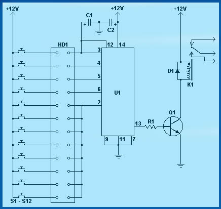
Circuit diagram schematics of electronic keys, electronic locks, digital electronic locks, transistor code locks, and combination electronic locks. The circuit schematics for electronic locking mechanisms encompass a variety of designs tailored to enhance security and convenience in access control systems....
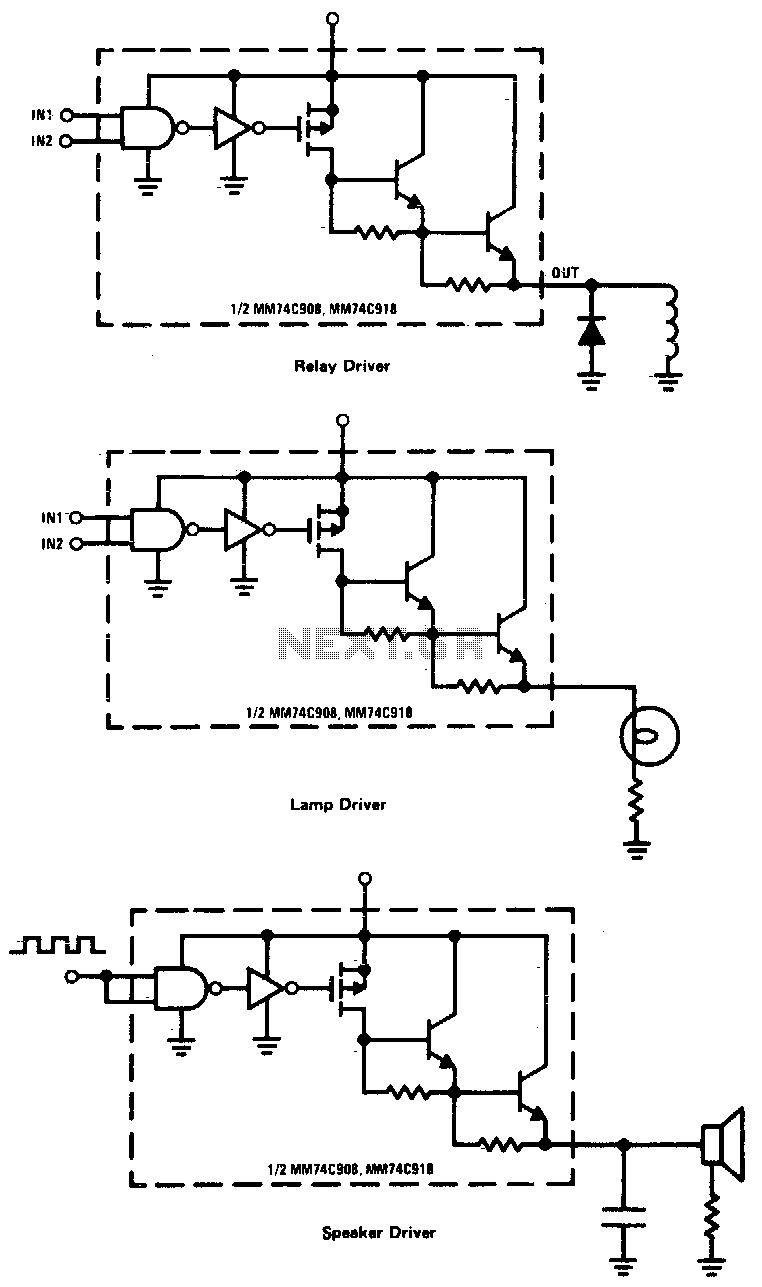
CMOS drivers for relays, lamps, speakers, and similar applications provide extremely low standby power consumption. When operating at Vcc = 15 V, the power dissipation per package is typically 750 nW when the outputs are not drawing current. Consequently,...

This temperature meter utilizes the precision micro power centigrade sensor IC LM35. The output voltage of the IC is linearly proportional to 10 mV per degree centigrade. The LM35 temperature sensor is a versatile and widely used device in electronic...