
10 Channel Graphic Equalizer by LA3600
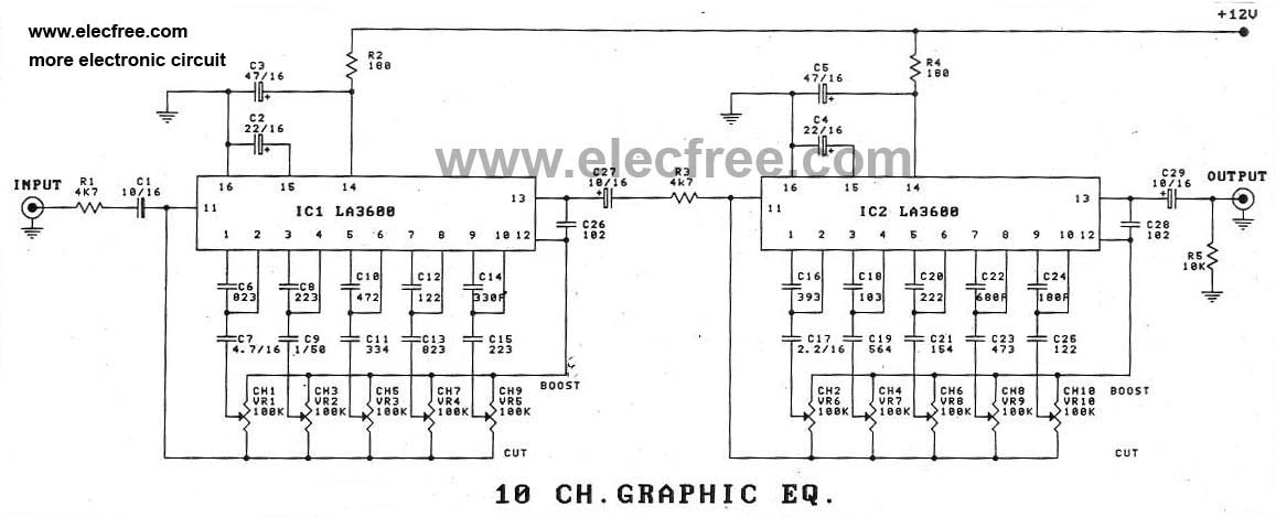
The design of a 10-channel graphic equalizer circuit utilizing the LA3600 integrated circuit (IC) offers enhanced audio processing capabilities. This circuit can be constructed by expanding the basic architecture of a 5-channel equalizer to accommodate additional frequency bands, allowing for more precise adjustments of audio signals across a wider spectrum.
The LA3600 is an integrated circuit specifically designed for audio applications, featuring multiple operational amplifiers that facilitate the creation of a graphic equalizer. For a 10-channel configuration, the circuit layout will include two LA3600 chips, each handling five frequency bands. The frequency bands typically correspond to standard audio ranges, such as 31.25 Hz, 62.5 Hz, 125 Hz, 250 Hz, 500 Hz, 1 kHz, 2 kHz, 4 kHz, 8 kHz, and 16 kHz.
The design process begins with selecting the appropriate resistor and capacitor values for each band, which determine the gain and frequency response of the equalizer. Each channel will have its own gain control, allowing users to adjust the amplitude of specific frequency ranges independently. The output of each channel can be fed into a summing amplifier to combine the processed signals into a single output.
Additionally, the circuit will require a power supply that provides the necessary voltage and current for the LA3600 ICs. Proper decoupling capacitors should be placed close to the power pins of the ICs to minimize noise and ensure stable operation. The layout should also consider the placement of components to reduce crosstalk and interference between channels.
Overall, a 10-channel graphic equalizer circuit using the LA3600 IC enhances the audio experience by allowing for fine-tuning of sound characteristics, making it suitable for various applications in audio processing and sound reinforcement systems.In addition to using the LA3600 IC, was the 5 channel graphic equalizer. We can also be designed was the 10 Channel Graphic equalizer circuit. By connection.. 🔗 External reference
Related Circuits
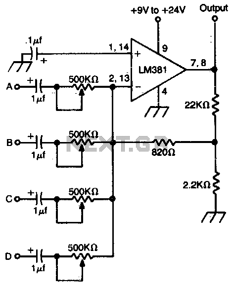
A high-gain operational amplifier combines up to four individually controlled input signals. The DC power source should be well-filtered (a battery is ideal), and the circuit should be well-shielded to prevent hum pickup. The high-gain operational amplifier (op-amp) circuit is...
The primary issue with the design of a stereo amplifier that includes a total bass driver is that the signals from the left and right channels eventually become combined. This summation process minimizes the separation between channels, compromising the...
Remotely controlled light dimmers used in theatrical and architectural applications employ a 0-10V control signal to adjust lamp brightness. In this context, 0V indicates that the lamp is off, while a 10V signal signifies that the lamp is fully...
With the rapid development of the social economy, the demand for electric energy continues to increase. In light of the diminishing availability of non-renewable energy sources, such as fossil fuels, many countries are recognizing the importance of energy conservation...

When discussing fan control, there are generally two methods: linear control and pulse-width modulation (PWM) control. Linear control is the most commonly used method, which involves reducing the voltage supplied to the fan. For a fan rated at 12...
The circuit was designed to create ten different frequency bands that can be processed by a single graphic equalizer to produce and maintain a predetermined frequency response. The described circuit is a graphic equalizer that utilizes a multi-band approach to...