
Touch Switch Circuits
The touch switch circuit is designed to provide a reliable method for controlling various electronic devices without the need for mechanical components. The integration of the CD4011 as a flip-flop allows for a stable on/off state that can be toggled with minimal physical interaction. The choice of resistors with a high resistance value ensures that the circuit is highly sensitive to touch, making it suitable for applications where precise control is necessary.
The 555 timer's role in this circuit is crucial, as it introduces a timed response to the touch input. By adjusting the capacitor and resistor values connected to the timer, the duration for which the LED and buzzer remain activated can be customized, allowing for user-defined feedback when the switch is engaged. This feature can enhance user experience in practical applications, such as in home automation systems or interactive displays.
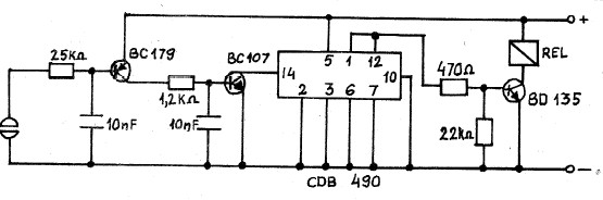
The current amplifier and decimal counter circuit further expand the versatility of the touch switch. By using the CDB490 counter, the circuit can provide visual feedback through the display of binary states, which can be useful in applications requiring status indication. The current amplifier ensures that the signal generated by the touch is sufficient to drive the subsequent stages of the circuit, thus maintaining functionality even with varying skin resistances.
Overall, the described touch switch circuits exemplify innovative applications of basic electronic components to achieve user-friendly and durable control mechanisms. Their simplicity and effectiveness make them ideal for both hobbyist projects and practical implementations in various electronic systems.A great collection of touch switch circuits. A touch switch is an electronic device that enables us to control a circuit by simply touching a sensor. The circuit as you can see from its diagram is very simple and only uses 8 components. The heart of the circuit is the IC CD 4011 that is connected as a FLIP-FLOP. Pins 9 and 13 of the IC are the «SET » and «RESET » contacts of the FLIP-FLOP. The IC is of the CMOS type and requires a very low current to in its gates to control it. This high sensitivity of the circuit makes the touch operation possible. The two gates are held at logic state «1 » continuously by means of the two resistors R1 and R3 that connect them to the positive supply rail. These resistors have a very large resistance of 10 Mohm. If we now touch a set of contacts the skin resistance closes the circuit between the corresponding gate and the negative supply rail.
The skin resistance for small areas of the skin is normally much lower than 10 Mohm and the gate is effectively brought to logic condition «0 » which makes the FLIP-FLOP change state. For any given state of the FLIP-FLOP touching the corresponding set of contacts will make the circuit to reverse its state of balance and in effect toggle the switch.
As a switch is used a relay driven by a transistor which is driven from the out put of the FLIP-FLOP. A touch switch is a switch that is turned on and off by touching a wire contact, instead of flicking a lever like a regular switch.
Touch switches have no mechanical parts to wear out, so they last a lot longer than regular switches. Touch switches can be used in places where regular switches would not last, such as wet or very dusty areas.
This circuit uses a 555 timer as the bases of the touch switch. You can learn more about 555 timers in the Learning section on my site. When the plate is touched the 555 timer is triggered and the output on pin 3 goes high turning on the LED and the buzzer for a certain period of time. The time that the LED and the buzzer is on is based on the values of the capacitor and resistor connected to pin 6 & 7.
The 10M resistor on pin 2 causes the the circuit to be very sensitive to the touch. A very simple touch switch circuit diagram can be constructed using this circuit schematic. This circuit will turn on /off an electronic relay using the same touch sensor. This touch switch circuit is composed from an current amplifier and a decimal counter circuit. the counter circuit is a CDB490 type and is capable to show at pin 12 states 1 and 0 that depends by the pulse applied of pin number 14. Pulses applied to pin 14 are provided by the current amplifier formed by that two BC transistors. It requires a 5volts power supply and can be used to turn on /off any other electronic circuit. This is a electronic touch switch ( on/off ) activated by skin resistance of finger. When the finger touch the on contact the a small current is delivered through skin to transistors to turn on the circuit.
The circuit remains on until the finger touch the off contact. This electronic touch switch designed with transistors require a 6 volts power supply circuit. The electronic touch switch circuit require few external components ( four transistors and four resistors ) and is very simple do build even for beginners. A very simple electronic touch switch can be constructed using this circuit diagram. This electronic touch switch is based on two transistors an can activate a relay, when the touch sensor is pressed.
The touch sensor can be constructed using a small piece of a printed circuit board ( two small tracks with a 2 mm distance between each other ). This circuit is powered using a 12 volts DC power supply, so the relay used for this project must be a 12 volts relay.
This circuit is working very simple, when both plates of the sensor are touched the skin resistance will activate the circuit. This is a easy to build on/off touch swi 🔗 External reference
Related Circuits
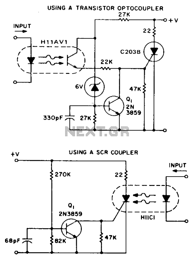
These two simple circuits provide zero voltage switching. They can be used with full wave bridges or in antiparallel to provide full wave control and are normally used to trigger power thyristors. If an input signal is present during...
This project describes how to build a "soft touch" switch. By "soft touch" we mean that you have to push once to set device ON and push again to set device OFF. This kind of switch works by latching...

Low power 5V switching regulator power supply. Visit the corresponding page for an explanation of the related circuit diagram. The low power 5V switching regulator is designed to efficiently convert a higher input voltage to a stable 5V output while...
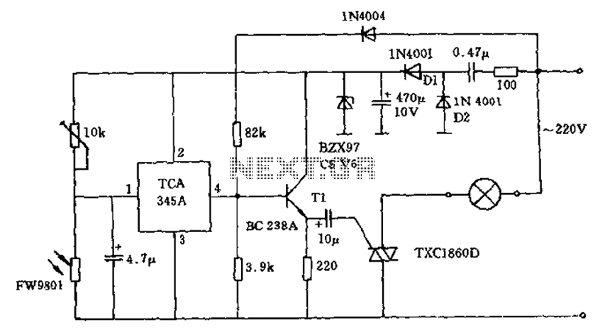
A 200W lamp switch control operates at a power supply voltage of 220V. It automatically turns the light on or off based on ambient illumination levels, specifically activating at approximately 100 lux. In low light conditions, a time-sensitive resistor...
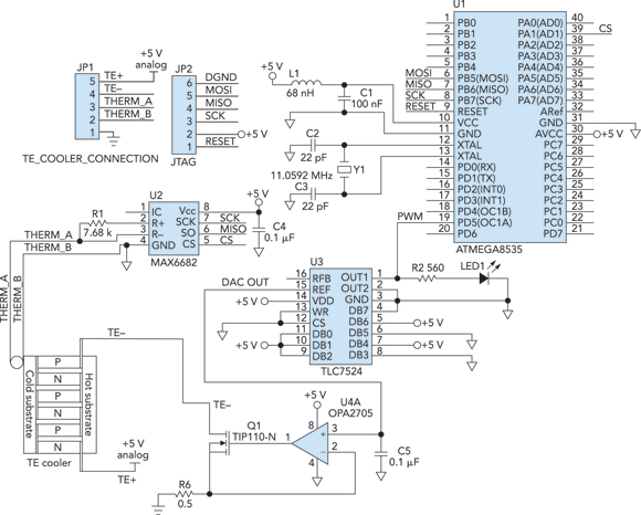
Cooling an instrument or device can enhance the signal-to-noise ratio (SNR) and extend the product's lifespan. For instance, the dark-and-noise signal of an infrared detector's output at room temperature can be significantly reduced when cooled. A custom cooling device...
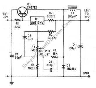
A switching voltage regulator circuit depicted in the schematic diagram can serve as a cost-effective solution for high-efficiency electronic circuit requirements. The switching voltage regulator circuit operates by converting a higher input voltage to a lower output voltage with minimal...
Warning: include(partials/cookie-banner.php): Failed to open stream: Permission denied in /var/www/html/nextgr/view-circuit.php on line 713
Warning: include(): Failed opening 'partials/cookie-banner.php' for inclusion (include_path='.:/usr/share/php') in /var/www/html/nextgr/view-circuit.php on line 713