
6 Channel RF Remote Control

The remote is powered by a 9-volt battery, connected to the terminal ends of M1. The negative terminal of the battery goes to "mass," while the positive connects to IC2, which stabilizes the voltage to 5 volts. IC2 (78L05) is equivalent to the more common voltage regulators but has a much lower consumption, making it ideal for battery applications. The heart of the remote control is IC1, a PIC16F84 microcontroller from the American company Microchip. With the software (free!) developed for the PIC, it serves as a basis for universal remote controls, with each pin assigned a specific function.
The keys are connected between pairs of pins such as "COL" and "ROW"; six out of the sixteen routes are utilized, leaving Col4, ROW3, and ROW4 disconnected. A simple delay network (R1, C1) provides the RESET power. Power is supplied to IC1 at +5V through pins 14 and 5 (ground). Capacitor C2 should be soldered as close as possible to the pin of IC1 to mitigate any power supply issues. The clock signal is generated by OSC1, a 4MHz ceramic resonator; if a quartz crystal (2-pin) is used, two small capacitors should be added as shown in the Nutchip base diagrams.
Pin DEFAULT (2) is set to +5 volts to select pre-stored codes, while pin RF (3) configures the chip in radio mode. The LED driver (pin 17) activates LD1 whenever a button is pressed. The output pulses for the transmitter come from pin OUT (18) and are sent to TX1, a 5V Aurel transmitter module. The transmitter requires an antenna tuned to 433 MHz connected to pin ANT. The arrangement of components on the PCB is flexible; spacers or a breadboard can be used for assembly, as precision is not critical.
The assembly process is straightforward, and with patience and precision, it can be completed by anyone. It is advisable to start with the lowest components (resistors) and gradually work up to the larger, bulkier parts. Using a socket for IC1 and the TX1 transmitter module is recommended. Care must be taken to avoid reversing the polarity of the LED, battery, capacitor C3, and TX1; if in doubt, refer to the COMPONENTS page for details.
The antenna connects to the ANT pad; a 16.5 cm piece of copper wire will suffice, although a professional model from Aurel, made of flexible black rubber, is recommended for enhanced performance. After assembling the board, and once all connections are verified, insert the PIC and TX1 module, then connect the battery, ensuring the polarity is correct. A multimeter can be used to check for stable 5V between pins 5 and 14 of IC1, as well as between specific pairs of legs on the TX1 module.
Once verified, insert the programmed PIC (using the file "picrmt.bin") and the TX1 module (with the component side facing outward) for the final test. The remote should activate upon connecting the battery, with the LED illuminating momentarily and then lighting up each time a button is pressed. If any components are unavailable, suitable replacements may be used with caution regarding pin-outs, which may differ from those specified in the provided circuit board design.
The integrated voltage regulator is a 5V regulator specifically designed for battery-operated devices, characterized by low power consumption and low-dropout operation. It can be substituted with a standard 78L05 (note the "L"), though this will significantly reduce battery life. The PIC can be either a PIC16F84 or PIC16F84A. The transmitter module is not critical and can be replaced with other 5V on/off modules operating at 433 MHz from different manufacturers (e.g., Mipot). For compact designs, a transmitter with a built-in antenna can be considered, though range may be limited.
In fixed installations (such as wireless doorbells, remote lighting, or controlling submersible pumps), the battery can be replaced with a small 9V DC power supply.This project creates a simple but valuable a wireless remote controller. He has as many as 6 channels (a rare feature for remote business) and transmits encoded MM53200 , UM3750 or UM86409 . Of course you can omit the button and make such a 2-channel remote control. It 'a pairing perfect for Nutchip , and is easy to build home-why do not you use special components: even the battery is a common 9-volt battery found in all supermarkets.
This diagram illustrates a remote fixed codes , ready to work immediately without adjustments. but plan appropriately the chip, you can also get codes like making a simple change. The remote is powered by a battery of 9 volts, connected to the terminal ends of the M1. The negative terminal of the battery goes to "mass", while the positive comes in integrating IC2 , which stabilizes the voltage to 5 volts. IC2 78L05 is equivalent to the more common, but has a much lower consumption making it ideal for battery applications ..
The heart of the remote control is IC1, a PIC16F84 microcontroller, the legendary American company integrated Microchip . With the software (free!) we have developed the PIC becomes a basis for universal remote controls, in which each leg has a specific function.
The keys are always connected between pairs of pins such as " COL "and" ROW : we will use 6 on 16 routes, leaving Col4, ROW3 and ROW4 disconnected. A simple network delay (R1, C1) provides the RESET power. The power to reach 5Volt IC1 through the legs 14 (+5 V) and 5 (ground). The capacitor C2 (weld as close as possible to the pin of IC1) clears any feeding problems. The clock is generated by OSC1, a ceramic resonator 4MHz 3-pin: to use to use a quartz (2 feet), you add two small capacitors as shown in the diagrams of the base Nutchip.
The foot DEFAULT (2) set to +5 volt select pre-stored codes, and the foot RF (3) shows the chip in the radio mode. The foot LED (17) driver LD1 is turned on whenever you press a button. The pulses for the transmitter out of the pin OUT (18) and go to TX1, a transmitter module to the 5Volt Aurel.
The transmitter module requires an antenna tuned on 433 MHz to be connected to pin ANT . Here are the opposite of the components on the PCB. You can also use "spacers" (using the same format and following the grid), or a breadboard spring (breadboard), because the assembly is not critical. The work is not difficult and with a minimum of patience and precision can be completed by all. Start with the lowest components (resistors), rising gradually to the highest and bulky. Better to use a socket IC1 and the module transmitter TX1 (a "strip" female will do). Be careful not to reverse the polarity of the LED, the battery, the integrated form of the capacitor C3 and TX1: if in doubt check the COMPONENTS page for details.
L ' antenna is connected to the piazzolina ANT , a piece of copper wire drive, 16.5 cm long, will be fine. Then if you want that extra touch, we recommend the professional model of Aurel, flexible black rubber.
Once the board (and after a further check of all connections) and the first to enter the PIC and the module TX1 connect the battery taking care not to reverse the polarity. Check with a tester between pins 5 and 14 of the base of IC1 have all of the 5 volt stabilized, as well as between the pairs of legs 3:01 p.m., 3:04 p.m., 3:13 p.m.
module TX1. Once the controls, remove the battery and insert the PIC (which you have previously programmed with the file "picrmt.bin") and the module TX1 (with the component side to the outside of the board). Are you ready for the final test! The remote should work now. Just connect the battery, the LED turns on for about a second, then turn on every time I press a button.
If you do not find all the components, you can make the sosituzioni with similar parts. Be careful though, to pin-outs, which can change from those provided in our printed circuit boards. The 'integrated stabilizer is a 5 volt regulator specifically for battery-driven appliances. Its characteristic is that they do not "eat" the battery to empty ( Low Power Consumption ) and power operation at low battery ( low-dropout ). Can be replaced by a common 78L05 (note the L), at the expense of battery life ( loooong less!). The PIC can be either a PIC16F84 or 16F84A. The recovery is the card for digital TV. The transmitter module is not critical and can be replaced with other modules on / off 5 volts and the frequency of 433 MHz of other producers (eg, Mipot).
If you want to make a tiny transmitter then consider a model with built-in antenna (but do not expect a great extent). In fixed installations (wireless doorbells, remote ignition of exterior lights, driving submersible pumps, etc) the battery may be replaced by a small DC power supply from 9 volts.
🔗 External reference
Related Circuits
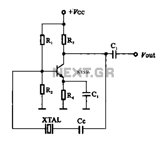
A series resonant circuit utilizing a crystal oscillator is illustrated. The crystal impedance reaches a minimum value at the series resonance frequency, resulting in a significant feedback amount. The crystal tuning capacitor (Cc) can slightly adjust the resonance frequency...
The HCS12 series of microcontrollers does not include dedicated internal digital-to-analog conversion hardware. Therefore, external hardware, such as a digital-to-analog conversion integrated circuit (IC), is required. To implement digital-to-analog conversion (DAC) in systems utilizing the HCS12 microcontroller, an external DAC...
Beeper and/or LED remotely-operated via mains supply line. Pressing the pushbutton of the transmitter, a sound and/or light alert is activated in the receiver. The system uses no wiring or radio frequencies: the transmitted signal is conveyed into the...
This circuit controls a load, specifically a DC brushless fan, based on temperature compared to a setpoint. The transducer used is a diode operating in the forward polarization regime. When forward-biased, the forward voltage drop across the diode exhibits...
The circuit utilizes an infrared (IR) receiver chip to capture IR signals from a remote control. This chip features a bandpass filter and a demodulator, resulting in a logic-level output. The controller section is based on a standard 8051...
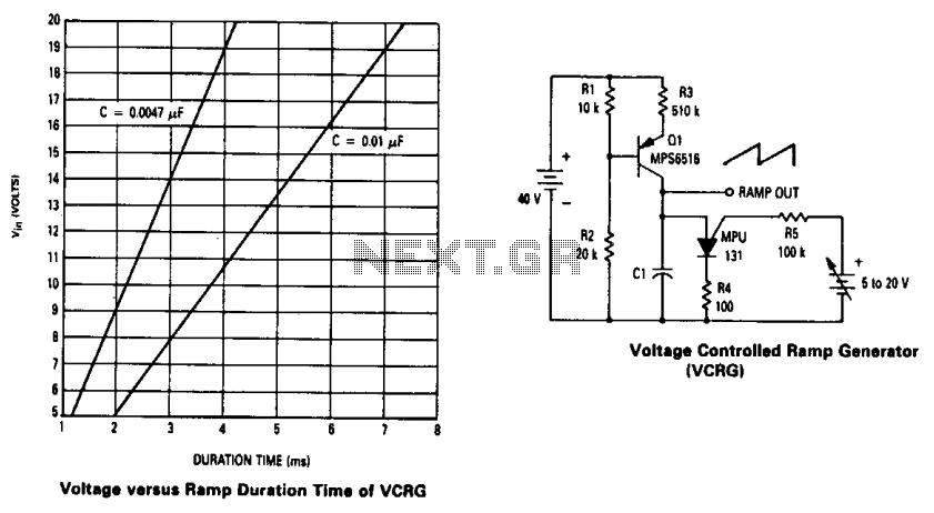
The current source created by Q1 in combination with capacitor C1 determines the duration of the ramp. As the positive DC voltage at the gate varies, the peak point firing voltage of the Programmable Unidirectional Thyristor (PUT) is altered,...