
6 digits dynamic display circuit
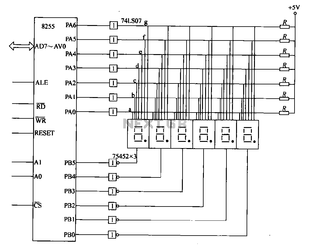
The circuit employs a PA 8255, which is a programmable peripheral interface that facilitates communication between microprocessors and peripheral devices. In this configuration, it manages the output for the display while the PB port is utilized for selecting specific bits that determine which segments of the display are activated. The hexadecimal numbers processed by the PA 8255 are essential for initializing the display, allowing for dynamic control of the visual output.
The 74LS07, a high-speed buffer/driver, amplifies the signals sent to the display, ensuring that the current supplied is sufficient to illuminate the LED segments effectively. This is crucial for maintaining visibility and performance, particularly in applications where the display may be subjected to varying ambient light conditions.
The use of a 75452 buffer/inverting driver enhances the circuit's capability to manage multiple display outputs. Each 75452 can handle two inputs, and since three are required to drive the six displays, this configuration allows for efficient signal management and distribution. The bit selection process is vital for ensuring that only the intended segments of the display are activated at any given time, thereby creating a clear and coherent visual output.
Overall, this circuit exemplifies a robust design for dynamic LED displays, utilizing well-established components to achieve effective results in digital representation. The method of cycling through the digits rapidly is a standard technique in multiplexing, allowing for the perception of simultaneous illumination of all six digits by the human eye.Shows - typical of six dynamic display circuit. In the figure, the PA 8255 end date display output code. PB port output bit election code. Let the display buffer is DISBUF, then complete the number (hexadecimal) to be taken after 8255 to initialize a display, using software decoding method determined to be 7-segment display control corresponding to the number displayed by the team and then port the code j output, and after 74LS07 drive to enlarge the display of data on each bus. In the end what a digital display, depending on the location of the election code. Only bit line select signal corresponding PB port after the drive goes low, the corresponding bit will not be emitting display.
If you are displayed in order from left to right, each successive digital display period of time (such as Ims), after the last digit is displayed, then repeat the process, so that the human eye can see is the 6-digit "simultaneously" display. Wherein 74LS07 to six drives, which raise the LED drive current for certain. 8255: As a 74LS07 only six drives, so the 7-segment requires two 74LS07 driving after PB port 75452 via buffer / inverting drive, 'as a bit selection signal.
A 75452 includes two internal buffers / drivers, each buffer red / driver has two inputs. Drive six LED display requires 3 75452.
Related Circuits
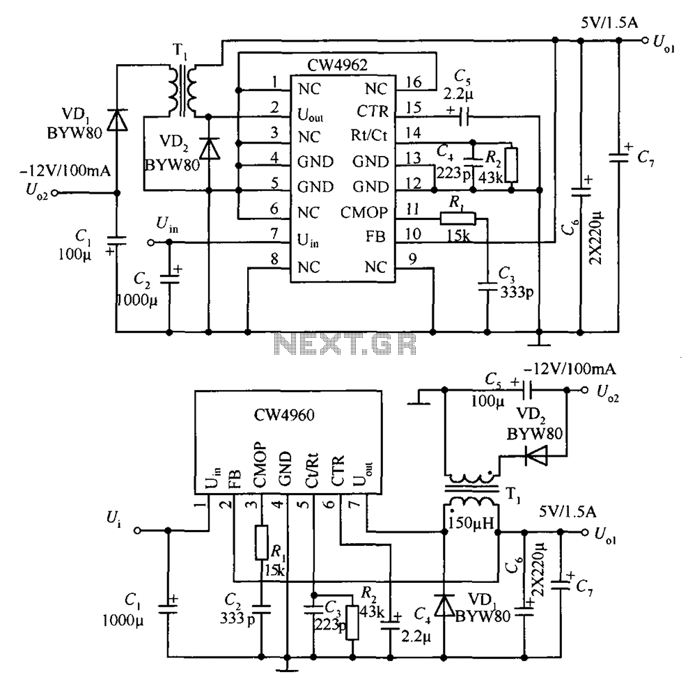
The circuit described is a stabilized power supply utilizing the CW4962 and CW4960 components, providing +5V at 1.5A and -12V at 100mA. The +5V output serves as the main power supply. The output circuit employs a transformer rather than...
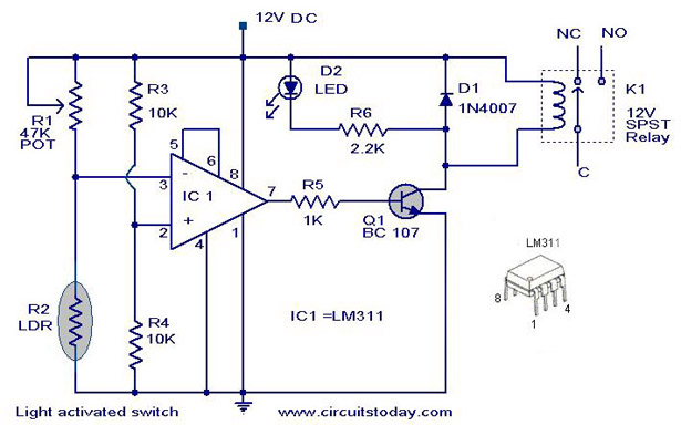
The following circuit illustrates a Light Activated Switch Circuit Diagram. This circuit is based on the LM311 integrated circuit, which functions as a voltage comparator. The Light Activated Switch Circuit utilizes the LM311 voltage comparator to control the switching of...
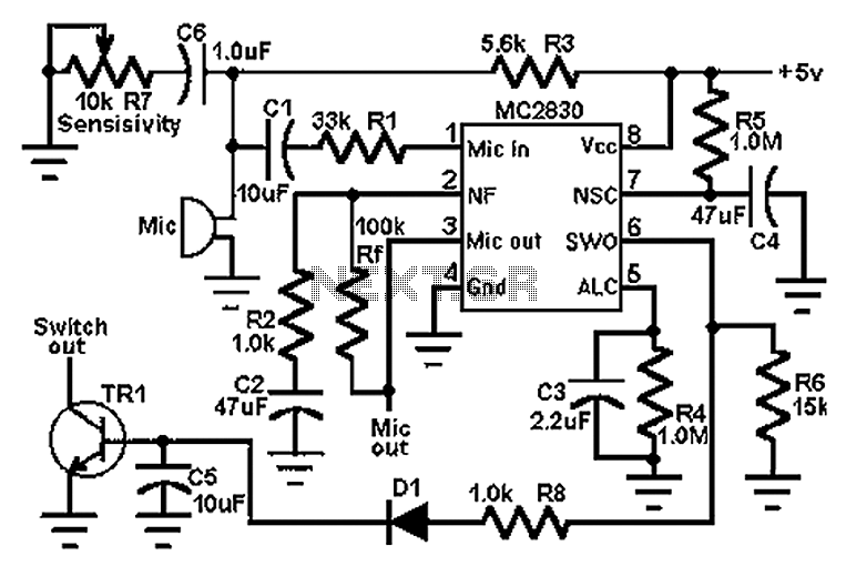
The circuit schematic utilizes the MC2830 voice circuit. Traditional voice circuits are unable to differentiate between speech and noise in the input signal. In noisy environments, such as those caused by switches, this limitation is significant. To address this...
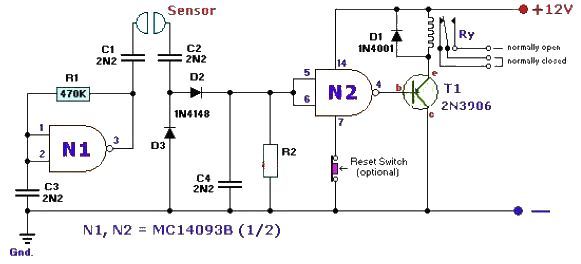
This fluid level sensor circuit is designed to use an AC sensing signal to prevent electrolytic corrosion on the probes. The rectified AC signal is utilized to drive a T1 transistor, which in turn activates a 12-volt relay that...
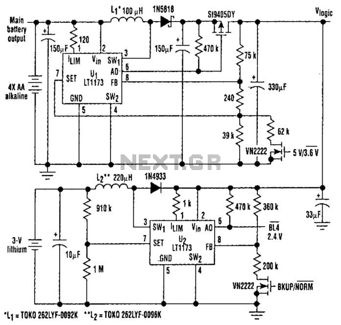
This unique logic-power-converter design allows for a switchable output of 3.6 V or 5 V at 200 mA using four AA cells. The supply features a MOSFET switch that can connect to a lithium backup battery, providing a 3.4...
A telephone line-based audio muting and light activation circuit. Frequently, when listening to music or watching television at elevated volume levels, it becomes difficult to hear a telephone ring, resulting in missed important calls. This circuit is designed to address...