
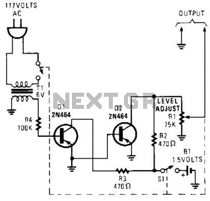
Low noise preamplifier circuit diagram of the speech

The MC2830 voice circuit is designed to enhance speech recognition in environments with significant background noise. The circuit operates by analyzing the characteristics of the incoming audio signals and distinguishing between speech and noise based on their waveform properties. The speech signals, which are dynamic and exhibit considerable amplitude fluctuations, are processed differently compared to the more consistent and stable noise signals.
In this configuration, the resistor R6 plays a crucial role in determining the sensitivity of the voice activation feature. By modifying the resistance value from 14K ohms to 7.0K ohms, the circuit's threshold for recognizing speech can be adjusted. This adjustment effectively alters the sensitivity of the circuit, enabling it to better filter out unwanted noise. The resulting change in sensitivity from 3 dB to 8 dB indicates a more robust performance in environments where noise levels are higher, thereby improving the reliability of voice detection.
The MC2830 circuit can be integrated into various applications, including voice-activated systems, noise-canceling devices, and communication equipment. The ability to differentiate between speech and noise not only enhances user experience but also increases the efficiency of audio processing systems in challenging acoustic environments. The schematic would typically include components such as capacitors for filtering, operational amplifiers for signal conditioning, and additional resistors to fine-tune the circuit's response to varying input conditions. Circuit schematic as shown below, using the MC2830 voice circuit is formed. Traditional voice circuit can not distinguish between speech and noise of the input signal. In a noi sy environment, the noise is often caused by the switch, in order to overcome this weakness. A voice circuit noise above, this is done using different speech and noise waveform. Speech waveform usually have wide variation in amplitude, and noise waveform more stable. Voice activation depends R6. Voice-activated sensitivity decreased, if R6 changes 14K to 7.0k, from 3 db to 8 db above the noise.
Related Circuits
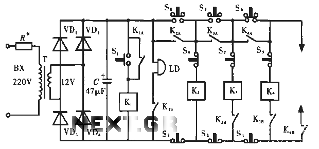
The circuit operates as illustrated in Figure 5-2a. It includes an alarm switch (S). When switch S is pressed, relay K is activated, which closes two normally open contacts. This action triggers the alarm bells. The alarm continues to...
White LEDs have a rated current at a voltage drop of about 3.3 to 3.4 V. It is ideal to be powered from the battery voltage which is slightly larger. Then there is the best energy used. In this...
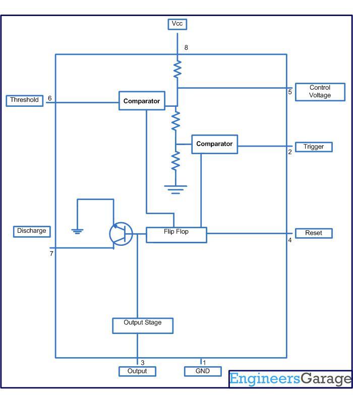
This circuit-based project demonstrates the operation of a 555 timer in astable mode to generate pulses with a time period of 0.5 seconds. These pulses can be utilized in various applications, such as blinking an LED or creating decorative...
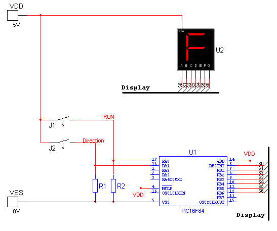
National Instruments Multisim now features microcontroller unit co-simulation capabilities, enabling the inclusion of a microcontroller, programmed in assembly or C code, within SPICE-modeled circuits. The MCU functionality in Multisim allows students, educators, and professional users to program MCUs in...
This generator circuit utilizes an overdriven amplifier to generate a 60 Hz square wave from the 60 Hz AC line. The circuit is suitable for line-operated applications as a clock source. The generator circuit operates by leveraging an overdriven amplifier...
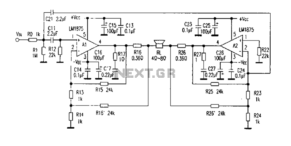
The DC current negative feedback BTL circuit illustrated in Figure 2 eliminates the standard BTL circuit capacitors C12 and C22, which affects the DC characteristics of the circuit. Resistors R16 and R26 function as sampling resistors, while R15, R16,...