
6 Transistor Tildens H-Bridge
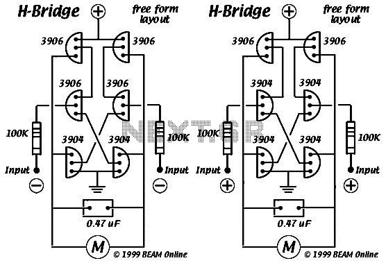
The 6 transistor Tilden H-bridge circuit is a specific configuration used for driving DC motors, enabling control over the motor’s direction and speed. This circuit employs six bipolar junction transistors (BJTs) arranged in a bridge configuration, allowing for both forward and reverse motor operation. The transistors are typically arranged in pairs, with each pair controlling the current flow through the motor in opposite directions.
In this configuration, two transistors are turned on to allow current to flow in one direction, while the other two transistors are turned off. To reverse the direction of the motor, the opposite pair of transistors is activated. The use of BJTs in this circuit allows for efficient switching and control, making it suitable for various applications, including robotics and automation.
The circuit is often used in BEAM robotics, where simple, efficient motor control is essential. The Tilden H-bridge's design minimizes component count while maintaining functionality, making it an attractive choice for hobbyists and engineers alike. Bruce Robinson’s explanation of the circuit provides valuable insights into its operation, highlighting the importance of proper transistor selection and biasing to ensure reliable performance.
In summary, the 6 transistor Tilden H-bridge circuit is a versatile and foundational design in the realm of DC motor control, with applications extending into various fields of electronics and robotics. Its historical significance and practical utility continue to influence modern circuit design.This diagram is certainly the 6 transistor Tilden H-bridge circuit; while not as old as the original basic H-bridge, this goes way back, and will be the basis for a lot of BEAM driver circuits. Bruce Robinson explaination about this circuit.. 🔗 External reference
Related Circuits

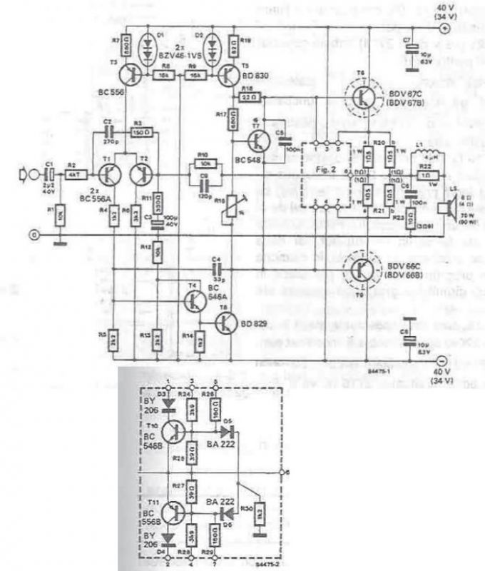
This circuit is a robust and efficient power amplifier suitable for various audio applications. It delivers 60W RMS output at a 50V supply with an 8 Ohm load. The design is user-friendly, allowing for the use of non-critical components...
Figure 2-32 (a) illustrates the time control diagram for a motor operated by switch S1. When S1 is set to position 1, the power driver circuit supplies current to the motor, enabling it to run. When S1 is switched...
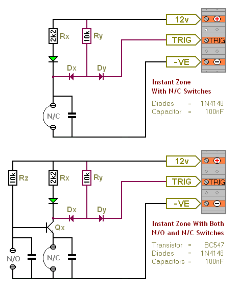
The Transistor Burglar Alarm System allows for the addition of multiple extra zones. The primary circuit is compatible with standard normally-closed input devices, including magnetic reed contacts, micro switches, foil tape, and passive infrared sensors (PIRs). An auxiliary circuit...
A high-power audio amplifier can be designed using power transistors and other common electronic components, capable of delivering a maximum output power of 90W. When using the specified component values, it can drive speakers with a 4-ohm impedance, resulting...
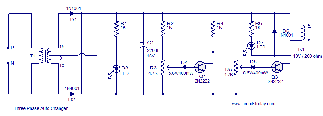
The following circuit illustrates a Three Phase Auto Changer Circuit Diagram. This circuit utilizes the 2N2222 transistor. Features include a transformer. The Three Phase Auto Changer Circuit is designed to automatically switch between different phases in a three-phase power system,...
This small transistor tester employs a simple visual indication system to perform a quick go/no-go check on both NPN and PNP transistors. When testing a functioning NPN transistor, the green LED (D1) will flash, while the red LED will...