
Power amplifier using transistors
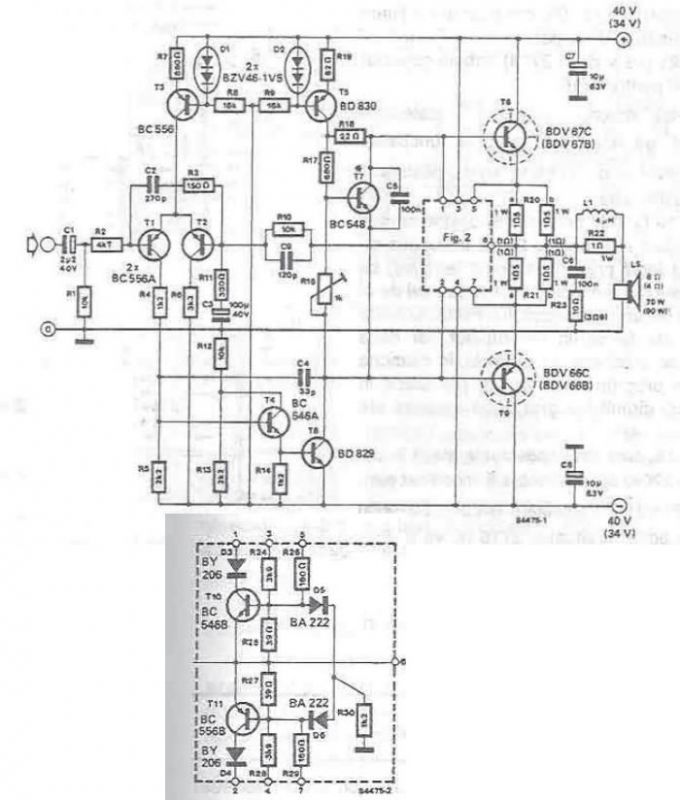
The high-power audio amplifier circuit is designed to deliver robust audio performance while ensuring thermal stability and protection against overloads. The circuit begins with the input stage, where the audio signal is introduced to transistor T1. This transistor operates as a common-emitter amplifier, providing initial amplification of the audio signal. The output from T1 is then fed to T2, which serves as a feedback mechanism to stabilize the amplifier's performance.
The differential stage, consisting of T3, maintains a constant current of 1 mA, ensuring that the amplifier operates within its optimal range. This constant current is crucial for maintaining linearity and minimizing distortion in the amplified audio signal. The control stage, formed by T4, T5, and T8, operates in Class A mode, providing a clean and linear amplification of the audio input. The relatively low current of 7 mA through this stage ensures that the power transistors T6 and T9, configured as Darlington pairs, can deliver high output power efficiently.
To accommodate a 4-ohm load, careful adjustments to the protection circuit are necessary. The specified resistor values (R24 and R28 at 3.9k ohms, and R26 and R28 at 220 ohms) ensure that the amplifier remains stable under varying loads. The removal of diodes D5, D6, and resistor R30 simplifies the protection circuitry while maintaining functionality.
The power supply for the amplifier is designed to deliver a rectified voltage of ±40V for an 8-ohm load, which is sufficient for achieving a maximum output of 70W. Under no load conditions, this voltage can rise to approximately ±47V, providing headroom for dynamic audio peaks. For operation with a 4-ohm load, the voltage levels adjust to ±34V and ±40V, ensuring the amplifier can still deliver high power without distortion or clipping.
In summary, the described high-power audio amplifier circuit effectively combines various electronic components to achieve a powerful and efficient audio amplification solution, suitable for driving low-impedance speakers while maintaining audio fidelity and system protection.Using some power transistors and some other common electronic components, can be designed a high power audio amplifier capable to provide a maximum output power of 90W. If the component values in parentheses are used can be connected speakers with 4 ohm impedance, in which case the amplifier maximum output power will be around 90 watts.
The input signal is brought to the transistor T1 and the reaction is taken on the basis of T2. Current through deferential stage is kept constant at 1 mA current source through the action of T3. The input signal for T4/T8 transistor is taken from the T1`s collector in combination with current source T5 forms a control stage class A for power transistors. Current through control stage is quite small (about 7 mA) as T6 and T9 are Darlington power transistors.
Protection circuit from Fig. 2 must also be changed when using a 4 ohm load. R24 and R28 values are then 3k9, R26 and R28 are 220 ohms, and D5, D6 and R30 are all eliminated. Rectified voltage for 70 W / 8 ohms version is ± 40 V to be in load, no load, this corresponds to about ± 47 V. At 4 ohms, these values are ± 34, respectively, ± 40 V. 🔗 External reference
Related Circuits
The Audio Power Amplifier is a crucial component in sound reproduction within audio systems. The LM3886 Audio Power Amplifier is a highly capable integrated circuit that can deliver 68 Watts of power with a 4 Ohm load and 38...
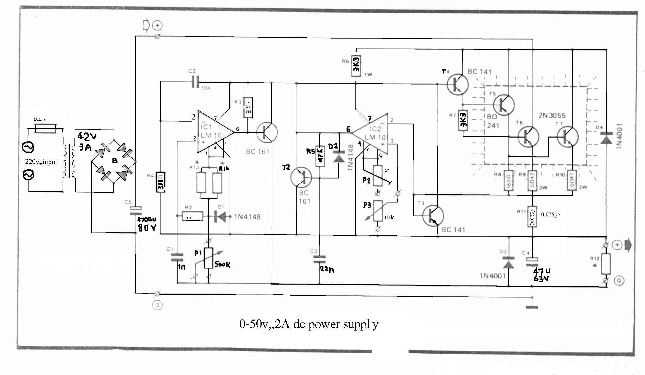
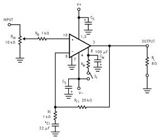
The LM10 integrated circuit (IC) is utilized due to its reference voltage feature, which is beneficial for DC power supply applications. By employing two ICs, it is possible to achieve different output voltages and current levels. The circuit includes...
An average ability amplifier characterized by acceptable overall quality, while being simple in construction. It is frequently used in live loudspeakers. The design incorporates high-quality FET transistors, specifically HEXFET technology, which are voltage-controlled rather than conventional bipolar transistors. The...
While conversing with a distant subscriber on the telephone, it is common to experience frustration due to faint audio that is barely intelligible. To address this issue, an inexpensive amplifier circuit is proposed. This circuit can be easily assembled...
The electronic diagram of the monophonic FM receiver made with TDA7088T is shown on Pic.4.12. If built with SMD components it can be placed in a matchbox, altogether with two button-type batteries. The operating principle of this device is...
The transformer has a 240V primary and has a secondary rated 24V at 2A. The bridge rectifier contains 4 diodes, their current rating needs to be high with respect to the transformers output current; if not the current may...